Page Contents
Creating Networks
From the simplest two host network to complex enterprise or carrier networks spanning the globe a network still comes down to nodes (switches and hosts) connected by links. One of the most fundamental network design and deployment decisions comes down to what to build/own and what to rent/lease. Typically we don't get much choice on whether we get to own or rent links or nodes, but we can have a wide choice in what technologies to use.
Once we need our network to extend beyond a single building we generally have to use other peoples networks to create the links we need. For example carriers offer many different WAN services as this example network map the the carrier Centurylink shows.
Issues with using other peoples networks
Incompatibility of address types
-
-
Example: A company uses private IPv4 addresses but wants to interconnect sites across the public internet. For more detail: RFC1918 specifies private IPv4 address ranges.
-
Related Example: Multiple users within a private address space need to share a singe public IP address → NAT (Network address translation). See Wikipedia and IETF RFC2663, section 4.1.2 "Network Address Port Translation (NAPT)" is what we usually just call NAT.
“NAPT extends the notion of translation one step further by
also translating transport identifier (e.g., TCP and UDP
port numbers, ICMP query identifiers). This allows the
transport identifiers of a number of private hosts to be
multiplexed into the transport identifiers of a single
external address. NAPT allows a set of hosts to share a
single external address.”
-
Compatibility of signal types
Example: I want to support a legacy telephone system and the only network infrastructure available is IP based. A standardized technique for doing this over IP or MPLS is called psuedowires
-
Pseudowire architecture RFC3985
-
Structure-Aware Time Division Multiplexed (TDM) Circuit Emulation Service over Packet Switched Network CESoPSN. See section 5.2 as an illustration of a straight forward way of packing DS0 signals into a packet. Also use this to illustrate compromises between latency and efficiency.
Incompatibility of layers
Example: I want to extend an Ethernet LAN between two sites and the only network available between this is an IP network.
Adaptation, Layering, and Tunneling
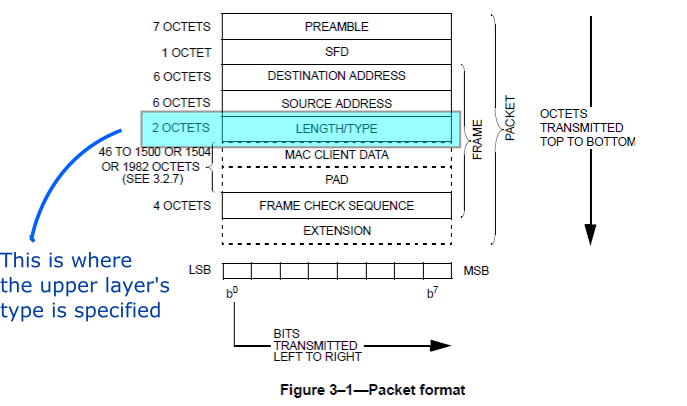
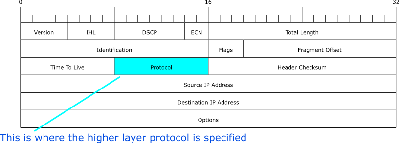
As part of normal network operations we expect to add layers of extra functionality above the link and network layer protocols we use. In fact both Ethernet Frames and IP datagrams contain explicit areas in their headers to tell the reciever what type of payload they are carrying. See Figures 1 and 2. In addition the next layer protocol may need to do some extra work to aid in the transmission over the lower level. We generally call this process adaptation.
From RFC7042 we get a sampling of Ethertypes:
   0x0800  Internet Protocol Version 4 (IPv4)
   0x0806  Address Resolution Protocol (ARP)
   0x0808  Frame Relay ARP
   0x22F3  TRILL
   0x22F4  L2-IS-IS
   0x8035  Reverse Address Resolution Protocol (RARP)
   0x86DD  Internet Protocol Version 6 (IPv6)
   0x880B  Point-to-Point Protocol (PPP)
   0x880C  General Switch Management Protocol (GSMP)
   0x8847  MPLS
   0x8848  MPLS with upstream-assigned label
   0x8861  Multicast Channel Allocation Protocol (MCAP)
   0x8863  PPP over Ethernet (PPPoE) Discovery Stage
   0x8864  PPP over Ethernet (PPPoE) Session Stage
   0x893B  TRILL Fine Grained Labeling (FGL)
   0x8946  TRILL RBridge Channel
From IANA here are a sampling of IPv4 protocol numbers:
1 	ICMP 	Internet Control Message
2 	IGMP 	Internet Group Management
3 	GGP 	Gateway-to-Gateway
4 	IPv4 	IPv4 encapsulation
5 	ST 	    Stream
6 	TCP 	Transmission Control
7 	CBT 	CBT
8 	EGP 	Exterior Gateway Protocol
9 	IGP 	any private interior gateway
10 	BBN-RCC-MON 	BBN RCC Monitoring
11 	NVP-II 	Network Voice Protocol
12 	PUP 	PUP
13 	ARGUS 	ARGUS
14 	EMCON 	EMCON
15 	XNET 	Cross Net Debugger
16 	CHAOS 	Chaos
17 	UDP 	User Datagram
Access to and Links between IP Networks: PPP
Concept: PPP's main function is adaptation, that is it allows IP (and many other packet protocols) to run over various circuit technologies from old analog telephone modems to SONET/SDH (TDM optical).
PPP in general: https://en.wikipedia.org/wiki/Point-to-Point_Protocol.
Packets over “circuits” or other “packet” networks.
PPP is a very old protocol that has been extended many times and in many ways. Both in what it can carry and what it can carry it over.
The original standard RFC1661 is readable.
-
Encapsulation (really simple, based on HDLC framing.
-
Link layer control protocols. Also includes authentication protocols. Basic LCP sets things like maximum transfer size, and header compression options.
-
Network Control Protocols. For example needed to give an IP address. See for example "The PPP Internet Protocol Control Protocol (IPCP)" for the IP control protocol.
-
Almost every packet protocol ever invented has been put over PPP. See the Assigned numbers for the official list.
-
Example: Use of PPP to carry Ethernet (Bridging PDU) uses type 0031. The Bridging Network Control Protocol (8031). See RFC3518.
Three “phases”: (1) Bring up “physical” link, (2) Use LCP to bring up data link layer, (3) use NCP to bring up/configure network layer.
IETF PPP related concluded working groups:
http://www.ietf.org/wg/concluded/ppp.html (1989)
http://www.ietf.org/wg/concluded/pppext.html
Of Note: RFC 3255: Extending Point-to-Point Protocol (PPP) over Synchronous Optical NETwork/Synchronous Digital Hierarchy (SONET/SDH) with virtual concatenation, high order and low order payloads.
More on Adaptation
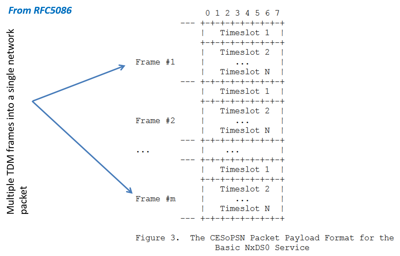
With PPP we saw the type of effort needed to put packets over bit or byte streams, i.e., we needed to introduce some framing to delimit the start and end of the packet and such. What about if we want to carry old fashioned voice DS0 circuits over a packet network? Couldn't we just gather a bunch of bytes from the DS0s and put them into a packet? Actually that is kind of what is done (Figures 3 and 4).
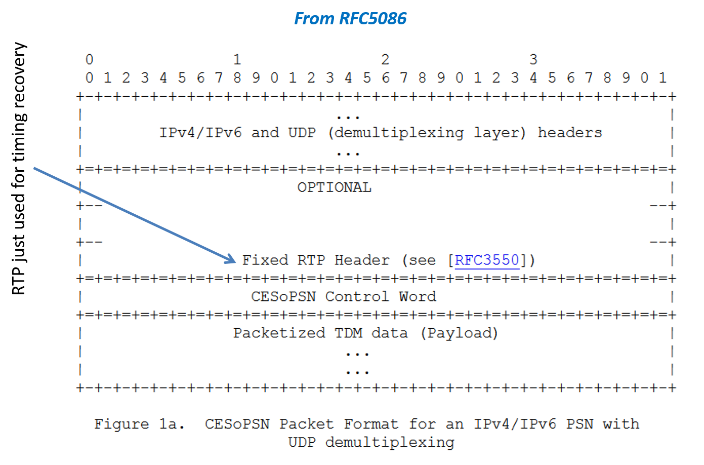
One tricky part of putting "circuits" over "packets" is timing recovery, i.e., making sure that the bytes get played out at the right speed at the other end of the network. From the above diagram we see that the CES service uses the Real-time Transport Protocol to help with this function.
From looking at the the previous headers for CES one should wonder about the efficiency of such an approach. When we talk about the efficiency of a digital communication scheme we generally mean the ratio of payload bytes (or bits) transported to the total bits transported.
Example 1: Consider an old fashioned T1 frame that carries 24 DS0 bytes along with 1 bit of synchronization overhead. The efficiency of such a scheme is:
$$ Efficiency = \frac{24 \times 8}{24 \times 8 + 1} = 99.482% $$
Example 2: Consider an Ethernet frame with 1200 bytes of payload. Assuming no padding we have 7 octets of preamble, 1 octet for SFD, 6 octets for destination address, 6 octets for source address, 2 octets for type, and 4 octets for the frame check sequence. This gives a total of 26 bytes of overhead. Hence the efficiency for this packet transmission is:
$$ Efficiency = \frac{1200 bytes}{1200 bytes + 26 bytes} = 97.88% $$
What if the payload was only 100 bytes?
$$ Efficiency = \frac{100 bytes}{100 bytes + 26 bytes} = 79.37% $$
For better efficiency we want to have large payloads for our packets. It looks like our old fashioned T1 line is more "efficient" than modern Ethernet transmission? Or is more analysis and context needed to make the assesment?
Latency in Real Time Communications
For real time communications we have an additional issue that can get in the way of efficiency and that is latency.
Example: For a 64 Kbps voice channel how long does it take to buffer up 100 bytes for transmission? What about 1000 bytes? Answer:
$$ time = \frac{100 bytes \times 8 bits/byte}{64Kbps} = 12.5msec $$
$$ time = \frac{1000 bytes \times 8 bits/byte}{64Kbps} = 125.0msec $$
For comparison the approximate distance from the US to India is 13600km and the speed of light is approximately 300,000km/s which would give a delay of approximately 45.3msec. Hence to achieve the highest efficiency in filling an Ethernet packet with DS0 voice samples would result in a delay equivalent to about three times the fiber optic transmission delay from the US to India. Hence we see that for real time communications there is a trade off between efficiency and latency.
What's Tunneling?
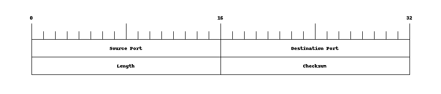
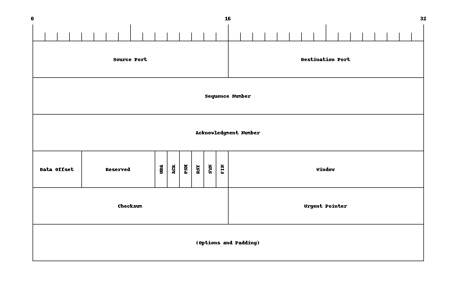
As we've seen with "normal" protocol layering, we frequently encapsulate payloads into additional "containers" to help "adapt" that payload to the link or network layer packet format. For example shown in Figures 5 and 6 are the UDP and TCP transport layer headers used with the IP network layer.
So how is tunneling different from the usual encapsulation and adaptation that we see in our layer protocol stacks? In general we use the term tunneling when the payload being encapsulated is a packet (or signal) from a layer equal to or lower than that the one we will be using to carry that packet or signal. We'll see or have seen examples of the following:
- Physical layer — DS0s — over IP
- Link Layer — Ethernet — over IP
- IP — say with private address — over IP — with public addresses
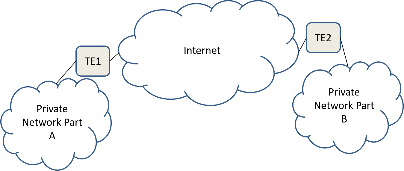
Typical network architecture with tunneling providing interconnection:
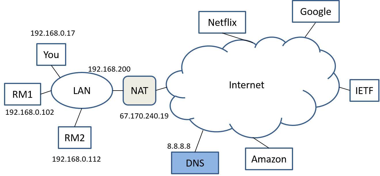
Network Address Translation (NAT), Half a Tunnel?: Somewhat similar to tunneling is NAT, Figure 8, which from a network diagram looks like half a tunnel.
Middleboxes
In the tunnel network diagram, Figure 7, we added special boxes, labeled TE, to denote the tunnel end points. Such processing may take place in a separate piece of network equipment or may be combined with other network equipment such as a router. In either case the tunneling functionality is very different from routing. In a home router typically NAT, Firewall, IP routing, Ethernet Switching, and wireless access point are all combined in the same physical box.
Things like tunnel endpoints, NAT, and Firewalls may exist in the IP "path" between source and destination and have different functionality than IP routers. At the IETF such entities are called middleboxes. RFC3234 discusses why these have become so important to the architecture of the internet and describes approximately twenty different types of middleboxes.
Popular Tunneling Protocols
There are many tunneling protocols in use today here is a short list of some we will consider in this course:
- IP-in-IP
- GRE
- L2TP
- VXLAN (Data center)
For some of the latest thinking on encapsulation techniques for tunneling see the following document from the IETF routing working group design team: encapsulation considerations.
IP in IP
What is the simplest approach that you could think of to connect two IPv4 subnetworks sharing the same private IPv4 address space across a public IPv4 network as shown in Figure 9?
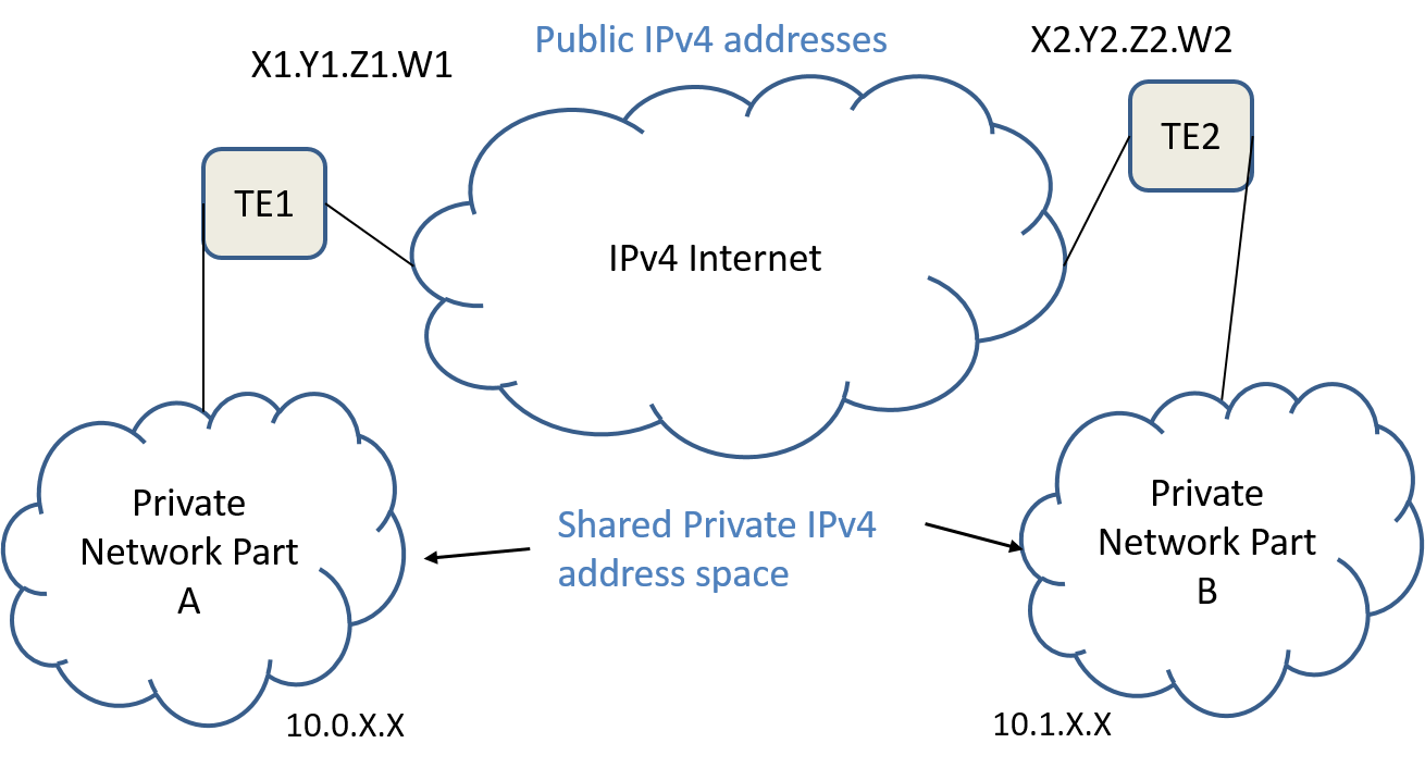
In this problem we have:
- A private network split into two pieces A and B
- Piece A uses private addresses in the range 10.0.X.X and has a single public IP address of X1.Y1.Z1.W1.
- Piece B uses private addresses in the range 10.1.X.X and has a single public IP address of X2.Y2.Z2.W2.
A simplistic approach:
- Whenever a router in part A sees a packet with an address for part B (10.1.X.X) it routes the packet to the tunnel endpoint TE1.
- Similarly for a router in part B seeing a packet with an address for part A.
- At tunnel endpoint TE1 we take the IPv4 packet bound for part B and put it inside another IP packet. For the destination address we use part B's public IPv4 address (X2.Y2.Z2.W2) for the source address we use part A's public IPv4 address (X2.Y2.Z2.W2).
- Similarly for processing at tunnel endpoint TE2.
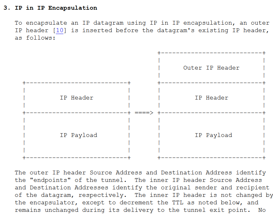
Is such an approach allowed? Yes. In particular, in the IP packet header the protocol field is used to indicate the protocol of the IP payload and the value of 4 is used for "IPv4 encapsulation". Such techniques are over twenty years old and are discussed in the informational RFC1853 (1995) and in a proposed standard RFC2003.
Is it available? Yes. There have been Linux kernel modules to support this for a very long time. Nice simple instructions for configuring such a tunnel can be found at LARTC.
Limitations: Limited to IPv4 over IPv4.
Generic Routing Encapsulation (GRE)
What if we want to tunnel some type of packet other than IPv4? What if we want to carry the encapsulated packet in something other than IPv4? The simplest approach would be to add a small header with information about what was being carried. Such as shown in Figure 11.
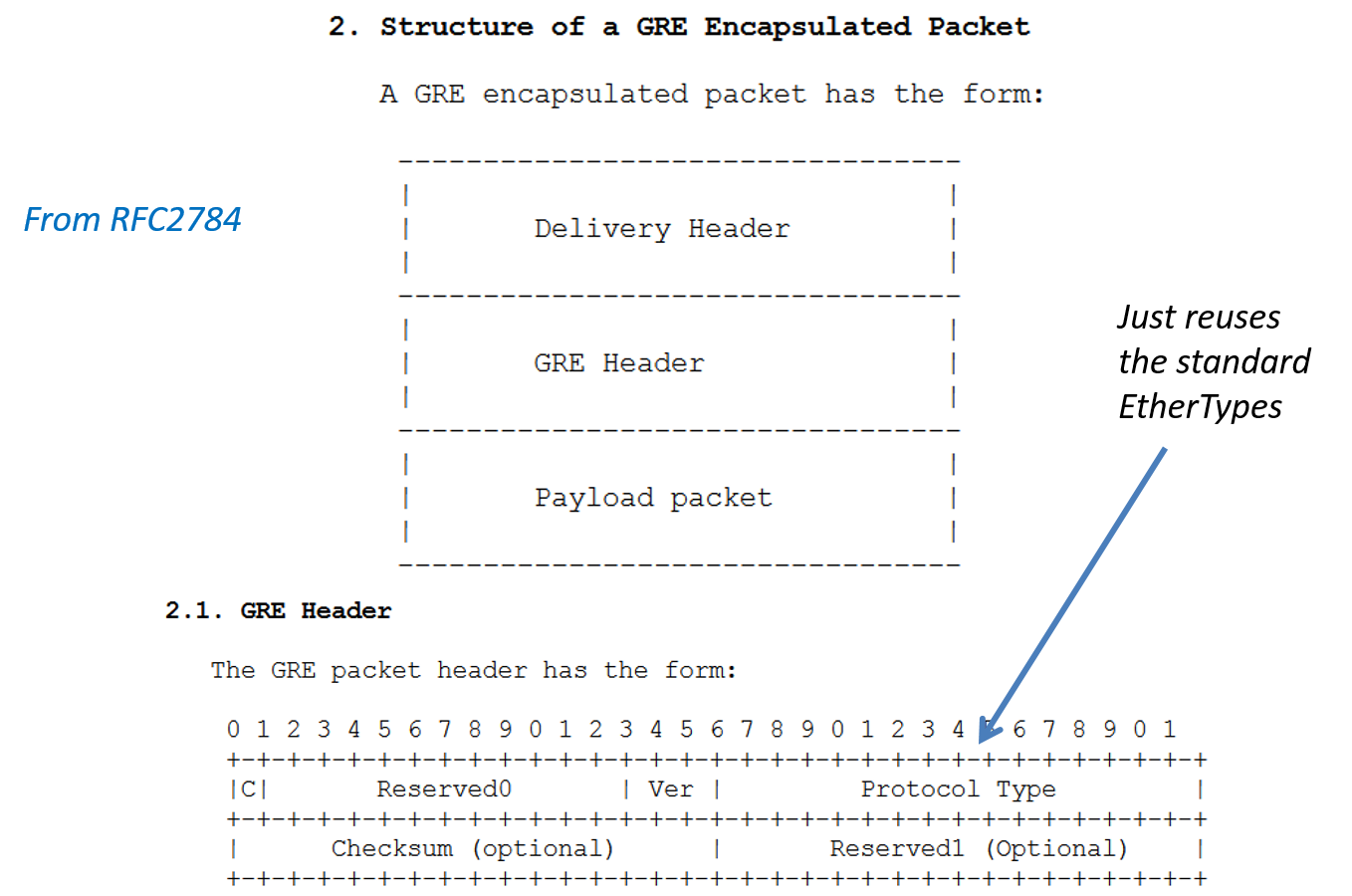
Generic Routing Encapsulation (GRE) is discussed in a number of IETF RFCs the best to review is RFC 2784.
In the GRE header:
- The "C" bit is used to indicate if the checksum is used.
- If the checksum is used, it covers the GRE header and payload.
- The protocol type field tells us the protocol of the payload and uses standardized Ethertypes. It is possible to put an Ethernet frame as the payload. In this case the protocol type would be 0x6558 per RFC1701.
Note when used over IPv4 GRE uses protocol number 47.
Is it available? Yes. GRE is available in many commercial products including routers and in the Linux kernel. Linux configuration examples are available from LDP.
Limitations: Does not provide much in the way of control protocols for the tunnel.
L2TPv3 (Layer 2 Tunneling Protocol)
We have now seen two tunneling protocols IP-in-IP and GRE. We saw that IP-in-IP was limited to IPv4 over IPv4, but that GRE had the capability to put about any protocol over IP. One thing that we didn't see with either protocol was support for dynamic tunnels. If you followed the links to the Linux configuration examples you would see manual configuration of each tunnel end point. Another potential issue is that GRE while very general isn't necessarily optimized to work with any particular layer 2 protocol. Finally, both IP-in-IP and GRE utilize IP directly and hence cannot be transported through a middlebox such as a NAT box.
The Layer 2 Tunneling protocol (L2TP) solves these issues by providing:
- A fairly comprehensive tunnel control protocol for the setup, teardown and maintenance of sessions RFC3931.
- Tunneling over UDP (RFC 3931 section 4.1.2) as well as IP. The UDP option allows for NAT traversal.
- In addition to providing a general approach to encapsulation based on PPP, L2TPv3 provides optimized transport of Ethernet and Ethernet VLAN frames RFC4719.
Virtual Private Networks
A nice set of definitions for VPNs and the problem they solve comes from RFC3809, June 2004:
Corporations and other organizations have become increasingly
dependent on their networks for telecommunications and data
communication.  The data communication networks were originally built
as Local Area Networks (LAN).  Over time the possibility to
interconnect the networks on different sites has become more and more
important.  The connectivity for corporate networks has been supplied
by service providers, mainly as Frame Relay (FR) or Asynchronous
Transfer Mode (ATM) connections, and more recently as Ethernet and
IP-based tunnels.  This type of network, interconnecting a number of
sites over a shared network infrastructure is called Virtual Private
Network (VPN).  If the sites belong to the same organization, the VPN
is called an Intranet.  If the sites belong to different
organizations that share a common interest, the VPN is called an
Extranet.
Network Contexts
The network context — who is connecting to whom, for what reason, etc... — greatly influences the types of problems encountered in creating a VPN and the technologies utilized.
One decomposition of the VPN networking problem from Mir2015:
- Remote Access VPN:
- Site-to-Site VPN:
- Intranet VPNs connecting sites within an organization
- Extranet VPNs connecting two different organizations
Another decomposition could be based on who provisions the VPNs:
- Provider Provisioned VPNs (PPVPN)
- The bulk of recent standard activitions at the IETF and IEEE have be focused on PPVPNs.
- Customer or Enterprise Provisioned VPNs
- Based on user configured tunnels
- Based on enterprise configured IEEE 802.1Q (Ethernet) VLANs
Still another decomposition can be based on the layer that the VPN provides service. At one point in time the IETF had three different working groups for layer 1, 2, and 3 VPNs respectively.
Finally when the VPN is offered by a service provider (carrier) they may offer different types of services such as:
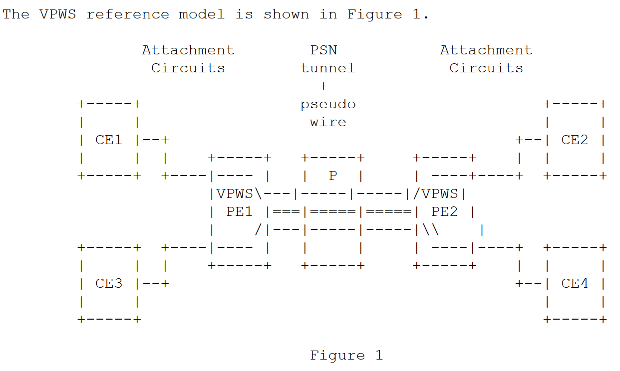
- Virtual Private Wire Service (VPWS) — like the point to point tunnels we've looked at.
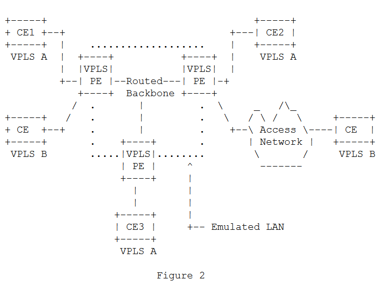
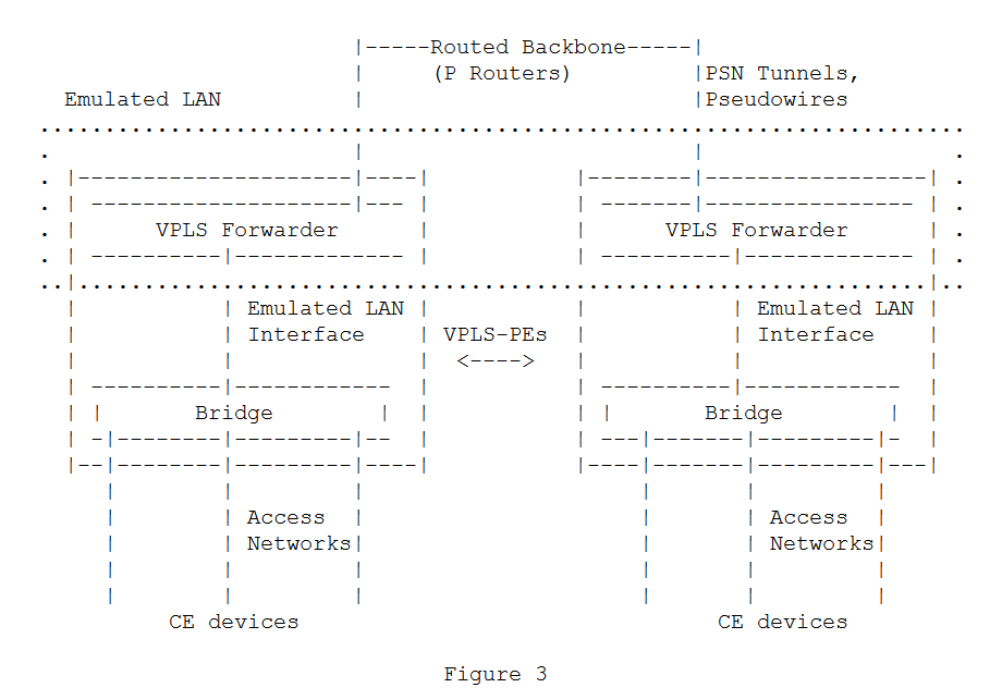
- Virtual Private LAN Service (VPLS) — which takes care of getting an Ethernet frame to the appropriate location as if all locations were on a single LAN.
Ethernet VLANs
Fundamental ideas of Ethernet VPNs:
-
Allow multiple Virtual “LANs” (really bridged networks) to share the same physical infrastructure. With each VLAN given a unique Identifier, known as a VID (VLAN identifier)
-
Restrict forwarding and broadcasting to individual VLANs, i.e., provides traffic isolation within a common network.
-
Enhances learning bridges to understand VLAN tags and such.
Examples: separate departments within a company, multiple tenant office spaces, multiple client applications within a data center.
VLAN Implementation Outline
The first thing we need to enable VLANs is a place in the Ethernet frame header to put the VLAN ID (VID). Recall the Ethernet frame structure shown in Figure 12.
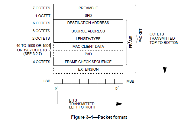
It seems that there isn't any space for a VID, i.e., all the fields are used. The trick that that IEEE adopted was to define new Ethertypes to support VLANs and then appending the "regular" Ethertype, i.e., the one that indicates the upper layer protocol as part of the payload as shown in Figure 13.
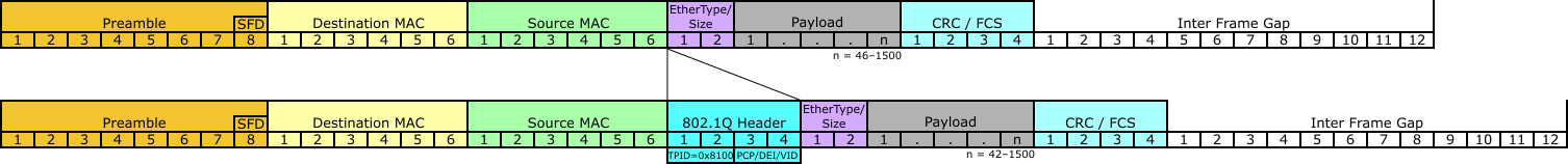
After the destination and source address a “tag header” is inserted and the FCS is recomputed. The header now consists of the Tag Protocol identifier (TPID) — essentially a new EtherType — and Tag Control Information (TCI).
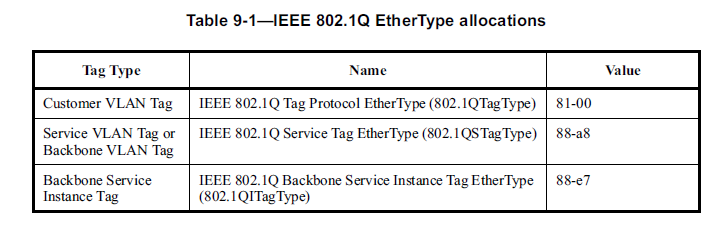
Figure 14 shows a list of the VLAN EtherTypes (from IEEE 802.1Q-2011, this is 1365 page document):
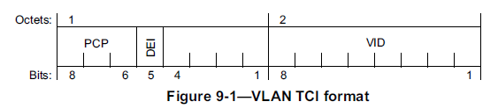
In addition to the VID = VLAN Identifier the Tag Control Information (TCI) field contains congrestion and QoS related subfields: DEI = Drop Eligible Indicator and PCP=Priority Code Point as shown in Figure 15.
Formally 802.Q describes VLAN functionality via an additional layer called the “Enhanced Internal Sublayer Service”.
How does Frame "tagging" work?
Who inserts VLAN tags onto packets?
Switches do! Switches can be configured to assign VIDs based on port or protocol.
How are VLANs configured in a typical case?
-
Two fundamental VLAN switch port types: “tagged” and “untagged”.
-
Some ports will be “access” ports
-
Some ports will be “trunk” (switch-to-switch ports)
-
Configure “access” ports as “untagged” and set the PVID (port VLAN ID) to the VID of the VLAN that the host should belong to. Untagged frames from the host will get the PVID added when entering the bridged network. Tagged frames for the host will have their tags removed.
-
Configure “trunk” ports as “tagged”. Such ports can belong to multiple VLANs and the tags are needed to restrict forwarding.
-
How can we get traffic to pass between VLANs? (IP) Route it!
-
Create a “tagged” port on one of the switches and configure it to belong to all VLANs that you want to route between.
-
Hook up a “lollipop” (aka “one-armed”) router to this multi-VLAN port.
-
Note that most Linux distributions have support for IEEE 802.Q tagging. In current Ubuntu this configured with the vconfig command that comes with the vlan package. Hence you could create an inexpensive lollipop router out of Linux.
-
Example low cost VLAN capable switch:
http://www.newegg.com/Product/Product.aspx?Item=N82E16833704093
http://www.tp-link.com/en/products/details/cat-5069_TL-SG3216.html
Bandwidth Efficiency via MSTP
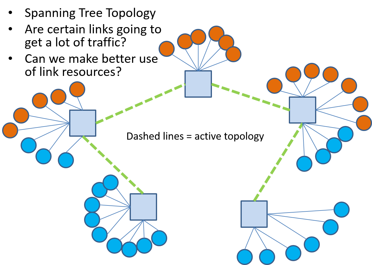
Ethernet VLANs help us achieve traffic isolation and restrict broadcast domains but what about better link utilization? The problem with bridged networks from a bandwidth/link utilization perspective is that they are tree topology networks! Consider the network shown in Figure 16 where the circles denote hosts and the color represents the logical grouping of the hosts, i.e., we want to put the blue and orange colored hosts into separate VLANs.
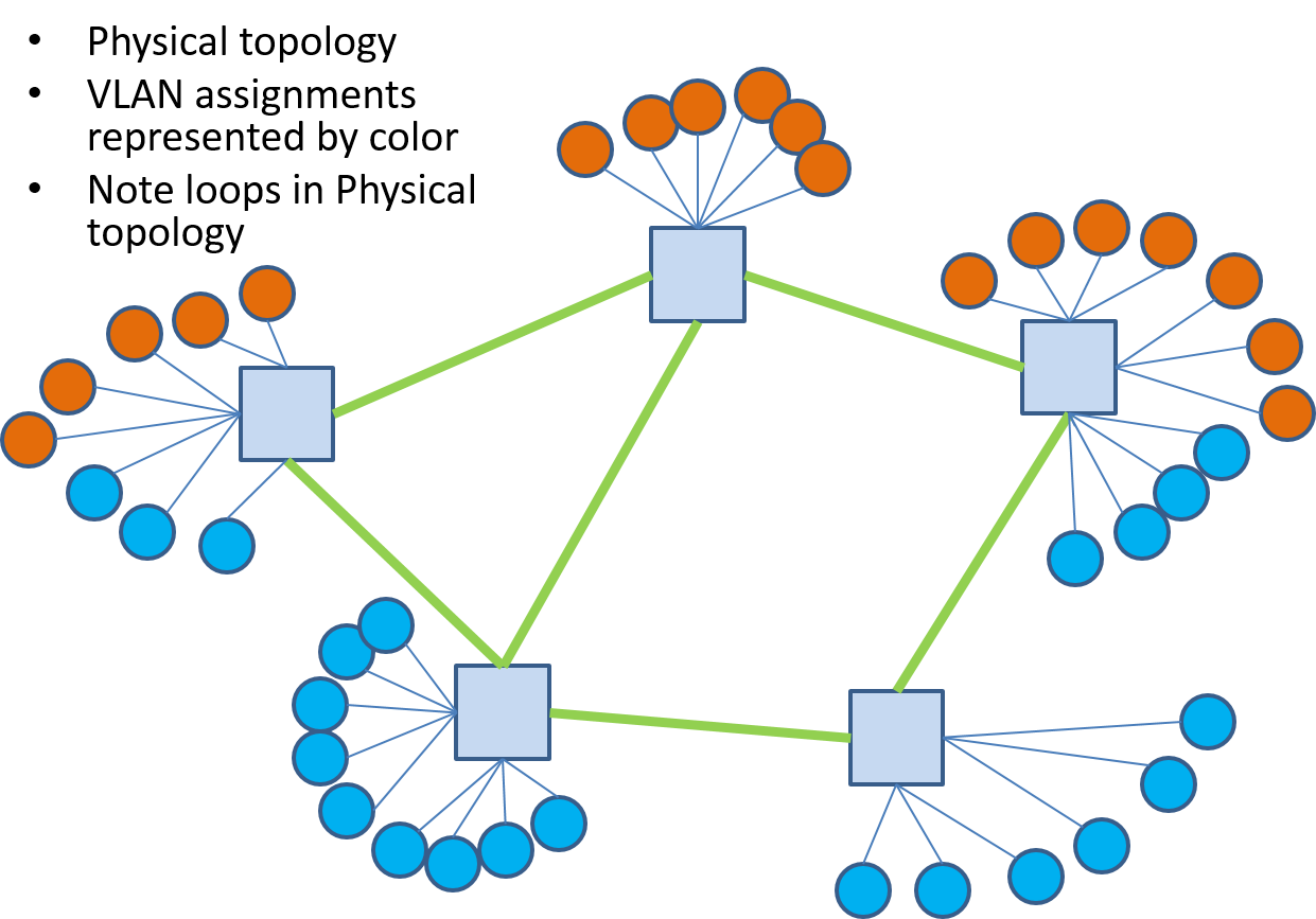
Ethernet spanning tree protocol prunes links that would result in loops, i.e., they are not used, and could give us a logical connectivity for this network as shown in Figure 17. A key property of tree topologies is that there is only one path between any two nodes. Looking at Figure 17 we see that for some of the blue hosts to communicate with their peers will require paths traversing up to four links and this traffic will cross links used by the orange nodes to communicate.
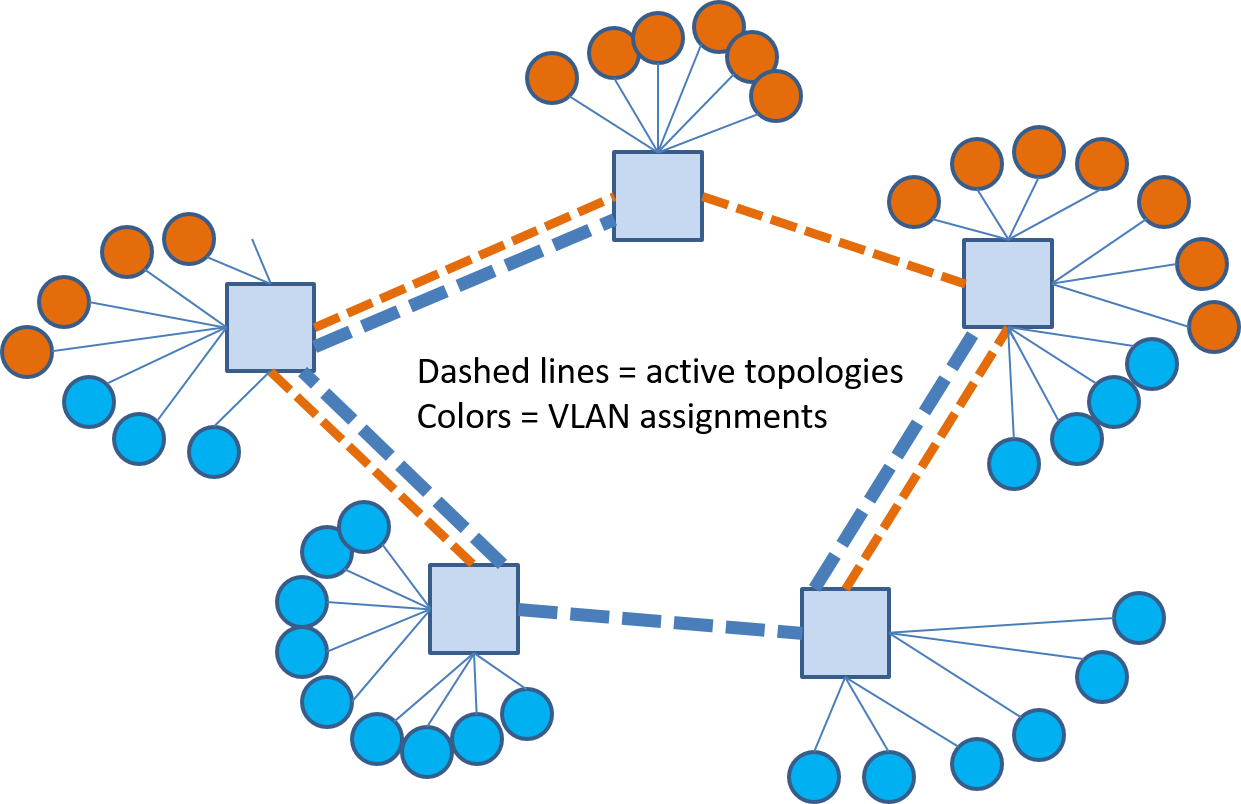
The multiple spanning tree protocol (MSTP) feature in 802.1Q allows us to assign different spanning trees to different VLANs. In our example network we could come up with different trees for the orange and blue VLANs as shown in Figure 18 where the different link colors are used to denote the two different trees in use and the the VLANs using them.
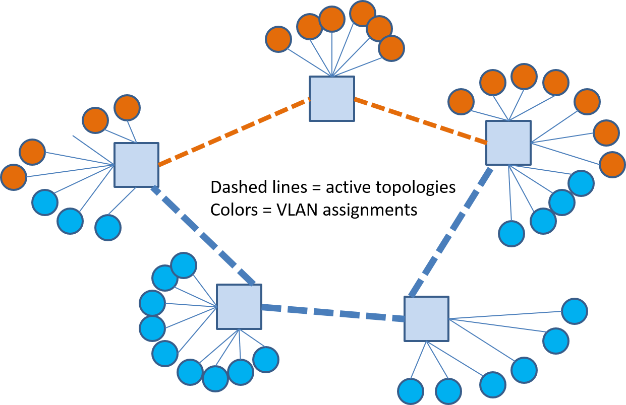
The advantage of this VLAN to tree assignment is even more obvious when we prune off links in each VLAN tree that will not be carrying traffic for that VLAN as shown in 19 where we can see that each link in this network is carrying traffic for only one VLAN. As we will see a bit more when we study SDNs that general mesh networks possess a great many trees and that trees play an important role in different traffic forwarding paradigms. In addition, SDNs will give us the most freedom to choose forwarding trees.
Notes on IETF VPN Efforts
Not required reading
The bulk of the IETF work on VPNs has concluded. It had in the past four working groups related to VPNs:
-
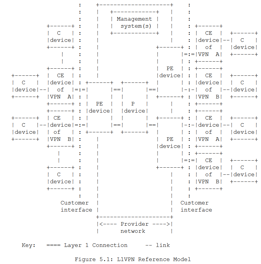
- "The L1VPN Working Group's task was to specify mechanisms necessary for providing layer-1 VPN services (establishment of layer-1 connections between CE devices) over a GMPLS-enabled transport service-provider network."
- Framework and Requirements for Layer 1 Virtual Private Networks (RFC 4847), April 2007.
-
- "The L2VPN working group was responsible for defining and specifying a limited number of solutions for supporting provider-provisioned Layer-2 Virtual Private Networks (L2VPNs). It will also address requirements driven by cloud computing services and data centers as they apply to Layer-2 VPN services."
- This working group produced a large number of RFCs both informational and standards track. Detailed standards track RFCs dealt with implementations via BGP and/or LDP. Other specific RFCs addressed ARP and Multicast issues. I'm only going to list a select list higher level documents (frameworks, requirements, etc...) here.
- RFC 4664: Framework for Layer 2 Virtual Private Networks (L2VPNs), September 2006.
- RFC 4665: Service Requirements for Layer 2 Provider-Provisioned Virtual Private Networks, September 2006. Read this first.
- RFC 7152: Requirements for Metro Ethernet Forum (MEF) Ethernet-Tree (E-Tree) Support in Layer 2 Virtual Private Network (L2VPN), March 2014.
- RFC 7209: Requirements for Ethernet VPN (EVPN), May 2014. It seems that previous Virtual Private LAN services (VPLS) have left a number of issues open and EVPN aims to address these.
-
- "This working group was responsible for defining, specifying and extending BGP/MPLS IP VPNs solutions (based on RFC4364 and RFC4659) for supporting provider-provisioned Layer-3 (routed) Virtual Private Networks (L3VPNs)."
- This working group produced a large number of RFCs. I'm only listing the high level requirements and framework RFCs here.
- RFC 3809 Generic Requirements for Provider Provisioned Virtual Private Networks (PPVPN), June 2004.
- RFC 4026 Provider Provisioned Virtual Private Network (VPN) Terminology, March 2005. Terminology and definitions for various types of VPNs.
- RFC 4031 Service Requirements for Layer 3 Provider Provisioned Virtual Private Networks (PPVPNs)
- RFC 4110 A Framework for Layer 3 Provider-Provisioned Virtual Private Networks (PPVPNs)
-
PPVPN. The Provider Provisioned VPN (PPVPN) working group disbanded around 2003 and seems to have fed its output to the L3VPN working group.
References
- [Mir2015] N. F. Mir, Computer and Communication Networks, Second edition. Upper Saddle River, NJ: Prentice Hall, 2015.