Page Contents
Introduction
If you've worked with a number of non-IP and non-Ethernet networking technologies such as MPLS, optical switching, or GMPLS, then concepts behind software defined networks (SDNs) may not seem like such a big deal. However in my experience teaching networking, particularly Ethernet and IP technologies, I can see where the difference between control and data planes doesn't get emphasized enough. For example how many students realize that a basic Ethernet switch has a control plane, i.e., the basic learning bridge "algorithm".
Getting hands on with SDNs makes this point clear and teaches many other lessons in networking. These notes contain tips for setting up an SDN testbed on your laptop and provide examples of programming SDNs. I plan on incorporating Mininet/SDN emulations more in future networking courses I teach. A more detailed outline is given below. If you have questions or comments send an email to Dr B.. Note: Last updated 2016.
-
A Virtual Machine for our Emulated Network
The folks over at Mininet have figured out a very nice way to emulate networks on a modern version of the Linux operating system. For isolation purposes, in case your emulated network runs amok, or if you don't run Linux directly on your laptop, you'll want to run Mininet in a virtual machine (VM). I use VirtualBox to run VMs on my Windows laptop, hence in the first section I give some extra tips on use and configuration.
-
Mininet and Python
You can do a fair amount with Mininet from the command line, but to get at more of its power and configurability you can work with it directly from the Python programming language. We give some tips and examples of how to do this.
-
Working with Networks/Graphs in Python
Here we go over one approach to working with network graphs in Python and give examples of shortest, widest, and arbitrary destination tree based forwarding tables for Ethernet switches.
-
Programming switches: First steps with Ryu or POX
Here we finally program all those virtual switches based on calculated forwarding tables and see the effects of different routing policies via round trip delays (ping) and throughput (iperf) in Mininet.
Working with the Mininet VM
The website Get Started with Mininet{target="_blank"} explains where to get a Mininet VM and possible ways to run it. The site Mininet VM setup{target="_blank"} contains further information on how get the Mininet VM up and running.
Windows Host Tips: You'll want the following additional open source software when running a Mininet VM (guest) on a Windows (host) machine
-
Putty
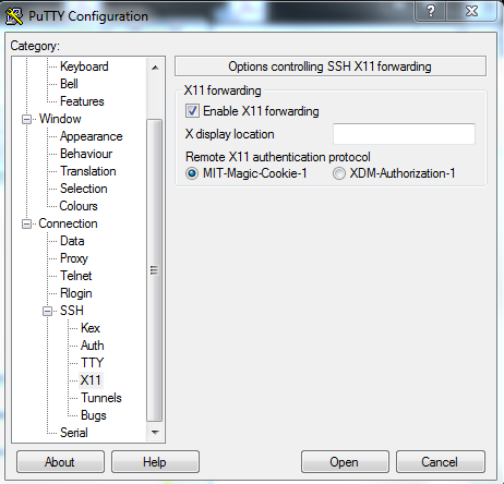
An SSH/Telnet (terminal thingy) client. Putty{target="_blank"} gives you a nice terminal to talk to the Mininet VM. It can also do SSH X11 forwarding (see Figure @fig:PuttyX11) which is important for getting displays of XTerms and Wireshark running in the VM on your Windows desktop.
Tip You can cut and paste to/from the Putty terminal window and Windows applications. To copy from the Putty terminal just hold down the right button and drag over the portion of the text in the window you want to copy. The highlighted text will be sent to the Windows clipboard. To paste something copied to the windows clipboard into the Putty terminal just click your right mouse button.
-
Xming
"Xming{target="_blank"} is the leading X Window System Server for Microsoft Windows" This means that you can "pipe" graphics out of your Mininet VM, receive them via Putty (above) and display them via Xming.
 {#fig:PuttyX11 width=365px}
Development Choices {class=unnumbered}
Linux VMs can be very nice development environments when working with open source code, however I prefer not to do my development work on the Mininet VM. I like a GUI particularly for my development tools and the Mininet VM doesn't come with one. Adding the Unbuntu desktop to the Mininet VM makes it larger and take longer to boot. In addition, Mininet keeps getting better and better (from 1.x, to 2.1, to now 2.2) hence I prefer to keep my development environment and run my controllers on my Windows host rather than the VM. So far this has worked fine with the following controllers: POX (Python), Ryu (Python), OpenDaylight (Java), and ONOS (Java). Your Mileage may vary.
Hence I add very little software to the Mininet VM. In particular I just add a few Python packages and will be using the Mininet feature for setting up remote OpenFlow controllers extensively.
VirtualBox Networking Choices {class=unnumbered}
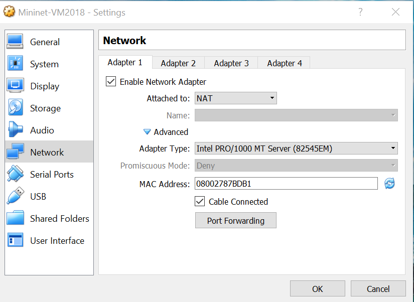
We need our VM running Mininet to be able to talk with the machine (or VM) running our SDN controller. There are three VirtualBox networking options that I have used and their pros and cons are listed below. I now recommend the NAT option with Port Forwarding.
-
NAT with Port Forwarding for SSH/SFTP. The NAT functionality allows the Mininet VM to have access to the Internet for downloads and the virtual switches you create in Mininet to access a remote controller (see configuration steps below for some tips regarding IP addresses). The port forwarding functionality allows for SSH console access and SFTP file manipulation.
-
The Bridged network option puts the VM onto your local area network. In this case the VM will usually need to obtain an IP address via DHCP or some other method. In my home network this works fine. However when I'm without a network, on a work network, or a university network that requires authentication to gain network access this option can be problematic.
-
In Host-only networking VirtualBox sets up a network (actually you can have multiple networks) within your host computer for connecting VMs to the host and possibly to each other. VirtualBox can also supply IP addresses via a DHCP server when using this mode. The downside is that your VM will not have Internet access.
NAT with Port Forwarding Configuration Example {class=unnumbered}
For your Mininet VM in VirtualBox open up the network settings and select NAT (if it isn't already selected) as shown. This gives the VM (guest) access to the Internet via the host. We'll only use this to add some Python packages via pip.
Next we need to configure port forwarding. One possible configuration is shown below utilizing host address 127.0.0.18 one of many available local loopback IPv4 address. I left the host port at 22 which is the default port for SSH/SFTP.
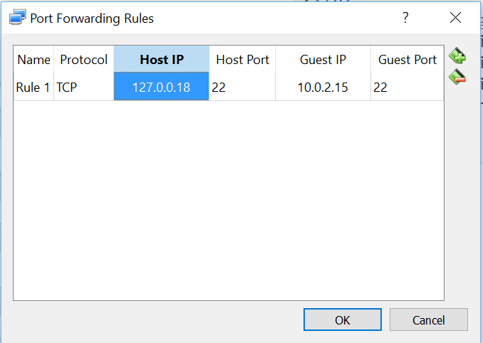
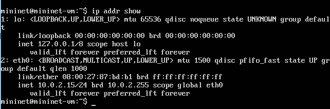
To get the guest IP address run the command ip addr show in the Mininet VM and use one of the non-loopback addresses shown. In my case there was only one 10.0.2.15 as shown below. You must use port 22 as the guest port.
Now you should be able to access your Mininet VM (on your host computer) by specifying the host address you used above in port forwarding (for me 127.0.0.18) in a program like Putty or if command line SSH is available via the command ssh mininet@127.0.0.18.
File Sharing {class=unnumbered}
Since I like to do my development on my Windows host, I need to get a few Mininet Python scripts and topology files from the Windows host to the Mininet VM. A particularly easy solution is to use a graphical SFTP client. On Windows I use WinSCP. I'll post some of my students recomendations for other OSes as I get them. Note previously I used VirtualBox's "shared folders" but setting this up on the MininetVM was somewhat lengthy.
Using Mininet
Mininet is written almost completely in Python so eventually you may want to access more
of its capabilities. This means that you can run Mininet from the interactive Python shell or
even an enhanced Python shell like IPython{target="_blank"}. The one
important
caveat is you must sudo into
the python shell, i.e., use the Linux command sudo python to start your
python session.
As an example you can enter the code in Code Example 1, a line at a time into an interactive Python shell to create a custom Mininet topology and run ping and iperf tests.
Code Example 1. Simple Python script ExMNsimple.py for generating a custom topology and running a few tests.
In Code Example 2. we create a bit more complicated network with two switches and three hosts. In addition we take advantage of a special Mininet link class called "TCLink". This class uses Linux's traffic control capabilities to allow us to specify a bandwidth limit and delay for each link. This will allow us to get even more information about paths across our emulated networks using ping and iperf.
If you've used Mininet a bit one thing you might not like about Code Example 1 is that you don't get the nice Mininet CLI that eases poking and probing your network. In Code Example 2 on line 18 we bring back the nice Mininet CLI. While you can enter Code Example 2 line by line into a python shell you can more easily just run it in your Mininet VM with the command sudo python ExMNtcSimple.py
in a terminal window.
Code Example 2. Simple Python script ExMNtcSimple.py for generating a custom topology with link bandwidth limits and delays specified, and bringing up the Mininet CLI.
Now lets try a few simple experiments at the Mininet command line. On line 2 of Code Example 3 we run a ping test from host "h1" to host "h2". From our topology description host h1 and h2 are both connected to switch s1 and have 10ms of delay on each of their links, hence without any other processing delays we'd expect a round trip time around 40ms. On line 6 we perform the same test between host h1 and h3 if we add up the delays on the links between h1 and h3 we get 10ms + 40ms + 7ms = 57ms one way. Hence we would expect a bit above 114ms round trip delay. Which we see on line 9 but not on line 8 (the first ping).
On line 10 we use iperf to determine the bandwidth available between h1 and h2. The link from h1 to s1 has a bandwidth of 20Mbps and from h2 to s1 has a bandwidth of 25Mbps. Hence the first link is the bottleneck and we expect roughly 20Mbps of throughput which is confirmed on line 12. On line 13 we test the throughput between hosts h1 and h3 in this case the link between s1 and s2 with a bandwidth of 11Mbps is the bottleneck as confirmed on lines 14 and 15.
mininet@mininet-vm:~/dev/FlowPractice/mnExt$ sudo python ExMNtcSimple.py
mininet> h1 ping -c 2 h2
PING 10.0.0.2 (10.0.0.2) 56(84) bytes of data.
64 bytes from 10.0.0.2: icmp_seq=1 ttl=64 time=45.6 ms
64 bytes from 10.0.0.2: icmp_seq=2 ttl=64 time=43.2 ms
mininet> h1 ping -c 2 h3
PING 10.0.0.3 (10.0.0.3) 56(84) bytes of data.
64 bytes from 10.0.0.3: icmp_seq=1 ttl=64 time=245 ms
64 bytes from 10.0.0.3: icmp_seq=2 ttl=64 time=116 ms
mininet> iperf h1 h2
*** Iperf: testing TCP bandwidth between h1 and h2
*** Results: ['18.9 Mbits/sec', '22.2 Mbits/sec']
mininet> iperf h1 h3
*** Iperf: testing TCP bandwidth between h1 and h3
*** Results: ['10.1 Mbits/sec', '13.6 Mbits/sec']
Code Example 3. Mininet CLI experiments with the custom topology from Code Example 2.
Now lets look a bit into the network that Mininet setup for us. Here we are using the Mininet CLI to execute some Python commands for us using its py command. On lines 1-6 we look at the IP addresses that Mininet has given the hosts and (not given) the switches. Hosts are given IP addresses in increasing order starting from an initial base. However, Mininet also allows you to set these yourself. Mininet does not give the switches IP addresses. We see on lines 7-10 that Mininet has assigned port numbers to all the ports on the switches. When we program switches with OpenFlow we need to use port numbers in our "matches" and "actions". Mininet also allows us to explicitly set port numbers on links. Finally lines 11-14 show the MAC (Ethernet) addresses that Mininet has assigned to the hosts. Mininet will use either random addresses, simple incremental number, or (as we'll use later) allow you to assign the MAC addresses.
mininet> py h1.IP()
10.0.0.1
mininet> py h2.IP()
10.0.0.2
mininet> py s1.IP()
127.0.0.1
mininet> py s1.ports
{<Intf lo>: 0, <TCIntf s1-eth3>: 3, <TCIntf s1-eth2>: 2, <TCIntf s1-eth1>: 1}
mininet> py s2.ports
{<TCIntf s2-eth2>: 2, <Intf lo>: 0, <TCIntf s2-eth1>: 1}
mininet> py h1.MAC()
26:51:25:0b:04:90
mininet> py h2.MAC()
ca:97:50:a0:f7:ee
Code Example 4. More Mininet CLI experiments with the custom topology from Code Example 2.
Breaking a Network (Don't do this in real life) {class=unnumbered}
Now lets try something you shouldn't do in real life. Create a network with a loop out of cheap Ethernet switches that don't run the spanning tree protocol. In Code Example 5, we have three switches and three hosts. Each host is connected to a different switch and the switches are connected in a nice reliable ring topology popular with optical networking folks.
Now when you run this code with the command sudo python ExMNtcSimpleLoop.py Mininet
will build the network and bring up the CLI. You won't get any indication there is a problem unless you try to ping between the hosts (go ahead try it!) and for me this failed. The other indications are that my task manager shows that VirtualBox is starting to use a lot more processing power for the Mininet VM, or if you've gotten WireShark working with your Mininet VM you'll see a huge flood of packets.
The reason for the packet flood is that the default Mininet controller implements a simple Ethernet learning bridge. No spanning tree protocol is present to prune off links that can induce loops so when the first packet arrives and is forward out all ports (since the address hasn't been learned yet) the flood starts! So the solution really is to use a smarter controller and in the following we'll illustrate how to do that. But first we'll take a detour into network/graph tools in Python.
Code Example 5. Simple Python script ExMNtcSimpleLoop.py for generating a custom topology with link bandwidth limits and delays specified and a loop.
NetworkX: Networks & Graphs in Python
NetworkX is a Python language software package for the creation, manipulation, and study of the structure, dynamics, and functions of complex networks.
We use NetworkX because of its well designed graph data structures, wide variety of implemented graph algorithms, and wide variety of supported graph file formats, including a nice efficient and extensible JSON based format. We recommend taking a look at the NetworkX tutorial but we'll give some simple examples here.
Important Note: These examples utilize version 1.11 of NetworkX. Version 2.0 of NetworkX introduced breaking changes and our examples will not run correctly with version 2.0.
Basic Graph Creation and an Algorithm
In Code Example 6, we show simple graph creation on lines 12-14, and some calls to some nice NetworkX graph member functions on lines 15-18. On lines 3-9 we give an example of a function to check for the validity of a given path against a given graph. We then test this function on lines 19-20.
Code Example 6. Simple Python script basicGraph.py for generating a NetworkX graph and a path validation algorithm.
A Graph with Attributes and JSON Export
What makes a graph into a good model for a network is the addition of attributes to the links (edges) and nodes (vertices) of the graph. This is easily done in NetworkX as shown on lines 7-9 of Code Example 7. Furthermore a network (graph with attributes) can be easily exported in a web friendly JSON format as shown on line 16.
Code Example 7. Simple Python script basicGraphAttribute.py for generating a NetworkX graph with link attributes and exporting the graph in JSON format.
More elaborate JSON Network Example and Path Computations
In Code Example 8 we show a fairly elaborate network described via NetworkX's JSON format with a number of our added attributes. See JSON network modeling for our network modeling approach. Looking at the "nodes" list that starts on line 4 we see a list of JSON objects representing the nodes. The only field required by NetworkX is the "id" field. For example on line 15 this is assign to "H8". We have additional fields for attributes such as IP and MAC addresses, node type (switch, host, etc...), and (x, y) coordinates for graphical representation.
The list of links starts around line 136. Each link object has a required source and target field which refer to the respective node ordinal in the node list. We've added link capacity, weight, and link end port numbering. The end ports are very helpful when working with Mininet and controllers since specifying these removes ambiguity and allows us to use the same file to describe the network to Mininet and to a controller. This is good for working with the network without or before you get discovery and host tracking working.
Code Example 8. JSON description of a more realistic network with attributes ExNetwithLoops1A.json.
In Code Example 9 we show how to read the previous JSON file into a NetworkX graph object (line 6). We then print a list of the ids of the nodes in the graph (line 7), the links in the graph along with their attributes (line 8), the hosts in the graph and their IP and MAC addresses (lines 9-11). Finally on line 14 we use NetworkX to compute the shortest paths from node "H8" to all other nodes. Lines 15-17 are use to print this information in a nice format.
Code Example 9. Python script to read the previous JSON file, print some information and do a path computation. ReadComp.py.
Computing Forwarding Tables {class=unnumbered}
NetworkX provides some path computation algorithms and one can look up and/or invent many others. However we need to do some bookkeeping to turn computed paths into forwarding (flow) table entries. In the following we will look at two different approaches to layer-2 (Ethernet) destination based forwarding. One based on shortest path trees and another based on widest path trees. In both cases we make the following assumptions concerning the network JSON description.
- Nodes identified as "hosts" are given IP and MAC addresses.
- Forwarding tables will only be set up to host destinations
- All links have node port number attributes. (Used to map links to switch ports)
- All hosts are "homed" to a single switch
In Code Example 10 we give code that computes layer-2 shortest path forwarding tables, i.e., like Ethernet SPB or TRILL but without their control planes. Around line number 51 in this file you see a single call to a NetworkX algorithm to compute all the shortest paths in a reduced network consisting of switches only.
Code Example 10. Python script to read a network JSON file and create shortest path based layer-2 forwarding tables for the network switches. ShortestPathBridge.py.
To show that in an SDN we aren't restricted to what has been done before, Code Example 11 uses a modified Dijkstra algorithm to compute widest (highest capacity) paths (trees) which are then used to populate the layer-2 forwarding tables. You can run Code Examples 10 and 11 with the network JSON file of Code Example 8. We'll later see how to get these forwarding tables into OpenFlow switches.
Code Example 11. Python script to read a network JSON file and create widest path layer-2 forwarding tables for the network switches. WidestPathBridge.py.
NetworkX and Mininet {class=unnumbered}
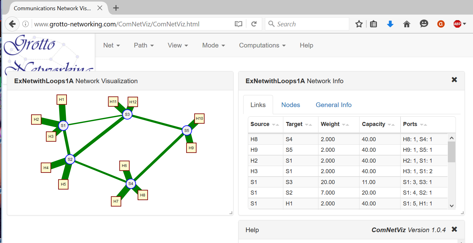
In Figure @fig:ComNetViz we show a bit more graphical and informative display of the JSON file of Code Example 8. In general I like to make a drawing of an example network using our communications network visulization app ComNetViz{target="_blank"} and then save and possibly manipulate the JSON file with a text editor or Python scripts. Remember JSON is a text format and is fairly readable and easy to edit. Although the ComNetViz{target="_blank"} app can add ports and IP/MAC addresses for you you can also modify the network with Python. In the file NetUtils.py{target="_blank"} you'll find examples of functions to automatically add port numbers to link end points and to assign IP and MAC addresses to hosts and can try applying them to the sample network ExNetwithLoops1.json{target="_blank"}.
 {#fig:ComNetViz width=500px}
Now lets bring the networks that we've saved in NetworkX JSON format to life in Mininet. A convenient Python script for doing this is given in Code Example 12. A few notes of features and caveats follow.
- This script must be run on the Mininet VM.
- You will need the NetworkX Python package installed on the Mininet VM.
- Assigned link capacities get translated into Mininet link constraints in Mbps.
- Assigned link weights get translated into Mininet link delays in ms.
- Constructs the Mininet network assuming a remote OpenFlow controller with the controllers remote IP address furnished on the command line.
- In the "main" portion of the script (around line 56) you can set a default remote IP address and network file name.
- Run this script with:
sudo python NetRunner2.py -f net_file_name -ip remote_ip_address
Code Example 12. Python script to read a network JSON file and create and run the network in Mininet. NetRunner2.py.
Programming switches with Ryu
In the previous sections we've looked into building and running networks in Mininet and on how to compute paths and forwarding tables. Now we need to take advantage of OpenFlow to program the switches in Mininet. To do this we'll need to leverage an OpenFlow controller framework. The landscape of OpenFlow controllers is fairly fluid and each one has its own learning curve. We are going to start with a minimalistic example utilizing the Ryu SDN controller to transfer the results of our previous forwarding table computations in the Mininet switches.
After this section is a similar section featuring the POX SDN controller which we initially used for SDN tutorials. As POX only supports OpenFlow 1.0 and hasn't been updated in over three years it seemed appropriate to demonstrate how to work with another controller in addition to POX.
Two complementary sources of documentation on Ryu are Ryu.ReadTheDocs and the Ryu Book. Note that the Ryu book is also available in Japanese, Chinese and Korean. Ryu is available a package from the Python Package Index and can be simply installed into your python installation with the command pip install ryu.
Running OpenFlow Applications in Ryu {class=unnumbered}
Like most OpenFlow controllers Ryu is a software framework within which you run you OpenFlow application. Hence one needs a way to start the framework and add in application components. In Ryu this can be done via a command line program, ryu-manager that is part of the Ryu package. In the following sections we'll use an alternative startup method that allows us to add command line options and a debugging interface.
Let's see how this works with a built in Mininet topology. In a terminal window for your Mininet VM enter sudo mn --topo linear,2,3 --controller remote,ip=192.168.56.101. This command will create a "linear" topology with two switches and three hosts attached to each switch. In addition this command line also tells Mininet to associate the switches with a remote OpenFlow
controller with the IP address 192.168.56.101 (You'll put in the appropriate IP address where you are going to run Ryu here).
Ryu ships with a number of SDN applications. We are going to run their simple learning bridge (switch) application that uses OpenFlow 1.0. On the machine that you installed Ryu type the command: ryu-manager ryu.app.simple_switch.
loading app ryu.app.simple_switch
loading app ryu.controller.ofp_handler
instantiating app ryu.app.simple_switch of SimpleSwitch
instantiating app ryu.controller.ofp_handler of OFPHandler
port modified 1
packet in 1 ea:b0:64:bc:0a:0f ff:ff:ff:ff:ff:ff 1
packet in 2 ea:b0:64:bc:0a:0f ff:ff:ff:ff:ff:ff 4
packet in 2 1e:57:6b:c9:e5:2d ea:b0:64:bc:0a:0f 1
Example Output 1. Output from a simple invocation of Ryu with its simple switch application (on controller host).
In addition on the Mininet VM terminal I can run some "ping" tests like so:
mininet> pingall
*** Ping: testing ping reachability
h1s1 -> h1s2 h2s1 h2s2 h3s1 h3s2
h1s2 -> h1s1 h2s1 h2s2 h3s1 h3s2
h2s1 -> h1s1 h1s2 h2s2 h3s1 h3s2
h2s2 -> h1s1 h1s2 h2s1 h3s1 h3s2
h3s1 -> h1s1 h1s2 h2s1 h2s2 h3s2
h3s2 -> h1s1 h1s2 h2s1 h2s2 h3s1
*** Results: 0% dropped (30/30 received)
mininet> h1s1 ping -c 3 h3s2
PING 10.0.0.6 (10.0.0.6) 56(84) bytes of data.
64 bytes from 10.0.0.6: icmp_seq=1 ttl=64 time=1.22 ms
64 bytes from 10.0.0.6: icmp_seq=2 ttl=64 time=1.12 ms
64 bytes from 10.0.0.6: icmp_seq=3 ttl=64 time=1.14 ms
Example Output 2. Mininet CLI interactions with the linear,2,3 topology (run on Mininet VM).
To see the other example applications that come with Ryu look in the site-packages/ryu/app/
directory of your python distribution, for me this is C:\Anaconda\Lib\site-packages\ryu\app.
Running your Application in Ryu {class=unnumbered}
Now we want to run our own OpenFlow application within Ryu. For our first example we will program our network to use either shortest path or widest path layer 2 (Ethernet) forwarding based on our previous computations. This way we can see first hand how SDNs and network optimization techniques allow us to trade off between bandwidth and delay rquirements. Code Example 13 shows the complete code. Before diving into detail we give a quick outline of the major pieces of functionality. In this and other examples based on Ryu we will not be launching our application via the ryu-manager but rather directly from our Python script so that we easily add command line arguments, and later a debuging command line interface.
Major Code Functionality Sections
-
We are going to use the same network description file we gave to Mininet for network creation to compute forwarding tables. In particular we will not be using the controller/framework to perform network discovery or host tracking. To do this we Ryu's option system on lines 31-38 to specify additional command line options. One for the network file and one for whether to use shortest or widest paths.
-
We set up our Ryu application class that will populate switch tables as the switches connect to the controller on lines 40-89.
-
We recover the python command line arguments and use them to launch the Ryu manager on lines 91-92.
Code Example 13. Ryu Python script which takes a network description file and populates OpenFlow forwarding tables as the switches connect to the controller. l2DestForwardStaticRyuNS.py.
Now let's delve a bit deeper into item 2 from above.
To work with Ryu you create a Python class that inherits from the RyuApp class. We show such a class starting around line 40 of Code Example 13 (we named the class L2DestForwardStatic). In Python class constructors are indicated by the
def __init__(self,...):
special member function. The first thing our constructor does is call its parent classes constructor on line 50. If you forget to do this your code will not work since the parent classes contructor sets up the applications event handling and processing within the Ryu framework.
The next thing we do is get the command line parameters, the netfile and widest_paths indicator, on lines 51-52. The first being our JSON network description file and the second a boolean to indicate whether we will use shortest or widest paths. You can see the precomputation of the forwarding tables around lines 55-59. Note that since Ryu is currently based on a multi-threaded cooperative multitasking infrastructure, i.e., eventlet you should use the Ryu application's logging facilities rather than print statements for debuging as I did on lines 53-54.
Before we can program the switches we need to wait to hear that the switches are up and connected to the controller. Per the OpenFlow protocol, a good time to do this is after controller receives a "switch features" OpenFlow message from a switch. This is the purpose of the code on lines 61-69. The odd syntax of @set_ev_cls(ofp_event.EventOFPSwitchFeatures) before the definition of the handle_SwitchUp() function is known as a Python decorator. The decorator, in this case, basically tells the Ryu framework to call our function when a particular class of event occurs. To see what OpenFlow events are supported and their names is a little tricky since the Ryu module ryu.controller.ofp_event dynamically generates the event classes from other python files that implement particular OpenFlow versions. The easiest way to see a list of Ryu supported OpenFlow events and their names is to type the following into an interactive python shell:
from ryu.controller import ofp_event
print(dir(ofp_event))  # Look at the items begining with the word Event
When the "switch features" message comes in we get the information on the switch that finished its handshake with the controller on line 67 (the "datapath" part of the message). We then call our function load_fwd_table() which sends all the forwarding table entries down to the switch. This function shown on lines 71-89, takes the datapath (switch) id and turns it into a switch name (line 77). The datapath id in our case is the Ethernet address we assigned to the switches in our JSON network description file (Mininet did this for us when we created the switch). We then get the forwarding table appropriate to this switch on line 79.
Running our example and seeing the effects of different forwarding schemes. Now we'll put together the pieces. We'll use our example network topology, our custom Mininet network runner, our two different forwarding table computation schemes, and our Ryu application.
-
On your Mininet VM you'll need: (a) the NetworkX Python library, (b) Our NetRunnerNS.py Python script, and (c) our example network JSON file ExNetwithLoops1A.json.
-
Use
sudo python NetRunner2.py -f ExNetWithLoops1A.js -ip remote_ip_addressto create and run the network within Mininet. Remember to do this on your Mininet VM ;-) The remote IP address should point to the machine where you will run your Ryu application. -
On the machine where you will run Ryu you'll need (a) NetworkX, (b) our example network JSON file ExNetwithLoops1A.json, (c) our two different Python programs for forwarding table computations (WidestPathBridge.py and ShortestPathBridge.py), and (d) Our Ryu application l2DestForwardStaticRyuNS.py.
-
We'll run our Ryu application from the directory where you have put the l2DestForwardStaticRyu.py, WidestPathBridge.py, and ShortestPathBridge.py files. Have a command or terminal window open here. Use the command:
python l2DestForwardStaticRyu.py --netfile=ExNetwithLoops1A.jsonfor shortest path forwarding orpython l2DestForwardStaticRyu.py --netfile=ExNetwithLoops1A.json --widest_pathsfor widest path forwarding. -
On the Mininet command line try a "pingall" test to see if you have connectivity between the hosts. If not check to see that your Ryu application came up and that Mininet connected to it.
-
Using the our application with shortest path forwarding try ping and iperf between hosts H1 and H9. I get output like that shown in Example Output 3.
-
Using the our application with widest path forwarding try ping and iperf between hosts H1 and H9. I get output like that shown in Example Output 4.
What's happening between these two examples is by changing the forwarding criteria from shortest paths to widest paths we've sacrificed some delay for a gain in bandwidth. Just a hint at the possibilities available when you start taking more control of your network :-).
mininet> H1 ping -c 2 H9
PING 10.0.0.3 (10.0.0.3) 56(84) bytes of data.
64 bytes from 10.0.0.3: icmp_seq=1 ttl=64 time=71.7 ms
64 bytes from 10.0.0.3: icmp_seq=2 ttl=64 time=69.4 ms
--- 10.0.0.3 ping statistics ---
2 packets transmitted, 2 received, 0% packet loss, time 1000ms
rtt min/avg/max/mdev = 69.467/70.600/71.734/1.164 ms

mininet> iperf H1 H9
*** Iperf: testing TCP bandwidth between H1 and H9
*** Results: ['10.3 Mbits/sec', '13.1 Mbits/sec']
Example Output 3. Mininet ping and iperf on our example network with shortest path L2 forwarding.
mininet> H1 ping -c 2 H9
PING 10.0.0.3 (10.0.0.3) 56(84) bytes of data.
64 bytes from 10.0.0.3: icmp_seq=1 ttl=64 time=92.3 ms
64 bytes from 10.0.0.3: icmp_seq=2 ttl=64 time=90.6 ms
--- 10.0.0.3 ping statistics ---
2 packets transmitted, 2 received, 0% packet loss, time 1001ms
rtt min/avg/max/mdev = 90.654/91.508/92.363/0.906 ms

mininet> iperf H1 H9
*** Iperf: testing TCP bandwidth between H1 and H9
*** Results: ['14.7 Mbits/sec', '17.6 Mbits/sec']
Example Output 4. Mininet ping and iperf on our example network with widest path L2 forwarding.
Doing more with Ryu: An Outline Application
In the previous section we used Ryu to set up our precomputed static routes. Here we give an "outline Ryu application" that exercises a number of OpenFlow interactions, shows how to get command line parameters, and shows how to bring up a python interface associated with the Ryu application for interactive investigations and debugging. Our outline applicaton is shown in Code Example 14. Below we describe and test our Ryu application's various features in a step by step fashion.
Code Example 14. An outline of a Ryu OpenFlow application that demonstrates a number of useful interactions. OutlineAppRyu.py.
-
Launching our Ryu application with custom command line parameters and an optional "backdoor"
- On lines 42-48 we use Ryu's configuration facilities to set up a boolean command line argument "notelnet". This argument is used to disable the telnet/python "backdoor" interface that we will be using to inspect and probe our Ryu application.
- On lines 69-71 we read this variable and bring up our "backdoor" interface if it is
False. - On lines 163-164 we read in the command line arguments and give them to the Ryu manager's
mainmethod. To run the program just typepython OutlineAppRyu.py. Note that we are not using theryu-managerprogram to launch our program, i.e., we are starting Ryu directly from our python program. You will need the IPv4 address of the machine you are running our outline application on in the next step.
-
Setting up an example network with Mininet
- We now need a network to control. On your Mininet VM use the command:
sudo mn --topo linear,3,2 --controller=remote,ip=192.168.56.1. Where the IPv4 address given is the address of the machine in step 1 (where you are running the controller). This creates three switches with two hosts connected to each switch with the switches arranged in a linear topology.
- We now need a network to control. On your Mininet VM use the command:
-
Listening and reacting to port status events
- On lines 107-123 is the code that responds to OpenFlow port status messages. The code
@set_ev_cls(ofp_event.EventOFPPortStatus)is a python decorator which tells Ryu the following function wants to receive port status change messages. The rest of the code parses the message and reports it via the logger. - Try the following at the mininet console:
mininet> link h1s2 s2 down mininet> link h1s2 s2 up- When I used these commands I saw the following from the console running our outline application:
I heard a port status change from switch 2 port 1 Port s2-eth1 is Down I heard a port status change from switch 2 port 1 Port s2-eth1 is Up - On lines 107-123 is the code that responds to OpenFlow port status messages. The code
-
Reacting to the connection of new switches
Lines 73-80 show our code for reacting to a switch features message. Here we receve the switch features message sent by a switch to the controller. We don't actually do anything with the message here, though it contains lots of useful information about the switch. What we do save is the datapath information on line 80,
self.switches[dp.id] = dp, so that we can later send OpenFlow messages to the switches. Now let's see how to inspect our running Ryu application from the optional "backdoor" we set up in step 1. From a command line on the machine that you are running our outline Ryu application type:telnet localhost 3000This should bring up a Python command line that is running with the outline application. I get the following output on my console (yours will depend on your python version):
Trying 127.0.0.1...
Connected to localhost.
Escape character is '^]'.
Python 2.7.11 |Anaconda 2.4.1 (64-bit)| (default, Dec  7 2015, 14:10:42) [MSC v.1500 64 bit (AMD64)] on win32
Type "help", "copyright", "credits" or "license" for more information.
(InteractiveConsole)
>>>
To get a reference to our outline application type the following code at this python command line:
from ryu.base.app_manager import AppManager
am = AppManager.get_instance()  # Gets the Ryu app manager
myapp = am.applications["OutlineApp"]  # Gets a particular app
From the
myappvariable we now have interactive access to all member variables and functions within our outline app. For example to see the number of switches that have connected to the controller type:print(len(myapp.switches)) # Prints 3 for the topology from step 2. -
Receiving packets sent to the controller from a switch
In the Mininet command line type
mininet> pingall(just the pingall part). Since we haven't set up any flow table entries all our pings should fail. However our code on lines 82-105 does keep track of packets received. In fact on lines 90-97 we keep count of the different types of Ethernet packets we have received in thepacket_in_typesmember variable. Let's look at this variable using our "backdoor" Python interface. Using themyappreference to our outline app that we showed you how to get in the previous step type:print myapp.packet_in_types
# I get: {2048: 0, 34525: 0, 2054: 105} Your numbers will vary.What do these number mean? The first number is the Ethertype in decimal and the second is the number of packets of that type we have seen. To see a number in hexadecimal format in python just type
hex(num)in a python shell. For example0x806 = 2054is the Ethertype for ARP messages. These are getting sent to the controller by default by the switches. Since we didn't program our controller to do any thing with the ARP messages they go unanswered and the pings cannot proceed. -
A method to create/delete a network of dumb hubs
As we saw in the previous step our controller seems to be receiving ARP packets, but we have no connectivity between hosts in our network. In a network without any loops we can acheive connectivity by sending only one OpenFlow message to each switch (and without involving the controller in packet processing). We do this by telling each switch to forward any packet received to all ports except the port it was recived on. This emulates what in the old, old, days of Ethernet what was called a "hub". Such flooding is extremely wasteful of network bandwidth and why "hubs" are no longer used.
On lines 125-141 we show how this is done. This method takes an optional boolean variable that indicates whether we want to add or remove the "dumb hub" flows. On line 127 we have a
forloop that iterates over all the swtiches (we got these in step 4). Theifstatement of lines 130-133 sets the OpenFlow command to either add or delete the flow. Line 134 sets the action to output the packet, with the psuedo output port "flood". On line 135 we specify a wildcard "match everthing" match. On lines 136-140 we assemble the flow mod message and on line 141 we send it to the switch.To run this method we'll use our backdoor python interface and the reference,
myappto our application that we learned to get in step 4. In the backdoor python shell type:myapp.make_dumb_hubs()After running the above you should see "pings" in Mininet working. To remove the flow entries that created the dumb hubs:
myapp.make_dumb_hubs(False)Now "pings" should stop working.
-
A method to intercept particular UDP port packets
The previous step used a very general "wildcard" OpenFlow match that matched all packets received by a switch. We usually want to be much more specific. On lines 143-161 we show a method that will set up (or remove) flows on all the switches to intercept UDP packets sent to a particular UDP destination port and forward them to the controller. This network feature works when we have the "dumb hubs" set up from step 6. The code for setting up the flow mod message is very similar to that of step 6 with the following important differences:
-
On line 155 we have a much more elaborate flow match:
match = parser.OFPMatch(dl_type=0x800, nw_proto=17, tp_dst=udp_port). Here, using OpenFlow 1.0, we tell the switch to match on IPv4 packets (Ethertype = 0x800), UDP protocol (Protocol number 17), and the UDP destination port given. -
On line 154 we are still using an output action, but now we are sending the packet to the "controller" psuedo output port.
-
On line 159 we set the flow mod message's priority to 20, while for the flows used to make the dumb hubs of step 6 we used a priority of 10. In OpenFlow when matches occur with flow table entries with wildcards the priority is used to determine with table entry to use. We need to have our intercept flow have a higher priority than the forwarding flow.
Let's test out this functionality. First from our backdoor python command line:
myapp.make_dumb_hubs() # Just to give network connecitityTo test out UDP packet interception we'll need two small python programs. One for sending UDP packets, Code Example 15, and another for receiving UDP packets, Code Example 16. We'll need to run these programs on the hosts within Mininet. We do this asking Mininet to create some "x-terminals" for some of the hosts:
mininet> xterm h1s1 h2s2 h2s3. Note you'll need some type of "X-Window" system working (see begining section on Mininet VM) for these to appear.In each of the host terminal windows type
ifconfigto see the IPv4 address of the emulated host. For me host h2s3 has IPv4 address 10.0.0.6. Currently our UDP sender program is configured to send packets to this address so we will run the UDP receiver program here. You need to get the both UDP sender and receiver programs onto you Mininet VM. From any host terminal window you have access to the Mininet VM's filesystem. Now run the UDP receiver programpython YOUR_PATH/udp_receiver.py. (set YOUR_PATH appropriately) It won't print anything unless it receives a packet on port 5015.Try running
python YOUR_PATH/udp_sender.pyin the xterms for h1s1 and h2s2. You should see a response on the receiver xterm. If not make sure you ran make_dumb_hubs() and got the IPv4 addresses in the sender and receiver correct.Now at the backdoor python interface run:
myapp.udp_intercept(5015)(5015 is the example UDP port make sure this port matches what was use in the sender/receiver code). Now try running the udp_sender script. The packet shouldn't get to the receiver, but you should see a message from our OutlineApp that it has intercepted it!
-
Code to test the UDP packet interception capability is given in code examples 15 and 16.
Code Example 15. Simple UDP packet sender. udp_sender.py.
Code Example 16. Simple UDP packet receiver. upd_receiver.py.
Programming switches with POX
In the previous sections we showed how to use the Ryu SDN controller to control OpenFlow switches here we demonstrate similar functionality using the POX SDN controller.
Documentation for POX is available from the POX Wiki. POX is written in pure Python and ships with the Mininet VM. However I prefer to install POX on my host so I follow their installation instructions{target="_blank"} to install the latest version. A couple of tips: (a) the POX wiki has a lot of good information, but it can be a little difficult to find so dig in! (b) look at their example files to see how to use features of POX.
Running OpenFlow Applications in POX {class=unnumbered}
Like most OpenFlow controllers POX is a software framework within which you run you OpenFlow application. Hence one needs a way to start the framework and add in application components. In POX this can be done via the command line. Let's see how this works with a built in Mininet topology. In a terminal window for your Mininet VM enter sudo mn --topo linear,2,3 --controller remote,ip=192.168.56.101. This command will create a "linear" topology with two switches and three hosts attached to each switch. In addition this command line also tells Mininet to associate the switches with a remote OpenFlow
controller with the IP address 192.168.56.101 (You'll put in the appropriate IP address where you are going to run POX here).
I've installed POX in a directory on my MS Windows host in the directory D:\pox now if I want to use the layer-2 learning bridge example application that ships with POX I would use the following command line (on my Windows host) python \pox\pox.py forwarding.l2_learning.
The first part of this command line starts the POX framework which then takes the rest of the command line as input and loads any modules, such as forwarding.l2_learning listed there. If all goes well you should see something like this on the controller host machine (for me my windows laptop).
POX 0.3.0 (dart) / Copyright 2011-2014 James McCauley, et al.
INFO:core:POX 0.3.0 (dart) is up.
INFO:openflow.of_01:[00-00-00-00-00-02 1] connected
INFO:openflow.of_01:[00-00-00-00-00-01 2] connected
Example Output 5. Output from a simple invocation of POX with its L2 learning application (on controller host).
In addition on the Mininet VM terminal I can run some "ping" tests like so:
mininet> pingall
*** Ping: testing ping reachability
h1s1 -> h1s2 h2s1 h2s2 h3s1 h3s2
h1s2 -> h1s1 h2s1 h2s2 h3s1 h3s2
h2s1 -> h1s1 h1s2 h2s2 h3s1 h3s2
h2s2 -> h1s1 h1s2 h2s1 h3s1 h3s2
h3s1 -> h1s1 h1s2 h2s1 h2s2 h3s2
h3s2 -> h1s1 h1s2 h2s1 h2s2 h3s1
*** Results: 0% dropped (30/30 received)
mininet> h1s1 ping -c 3 h3s2
PING 10.0.0.6 (10.0.0.6) 56(84) bytes of data.
64 bytes from 10.0.0.6: icmp_seq=1 ttl=64 time=41.4 ms
64 bytes from 10.0.0.6: icmp_seq=2 ttl=64 time=0.635 ms
64 bytes from 10.0.0.6: icmp_seq=3 ttl=64 time=0.088 ms
Example Output 6. Mininet CLI interactions with the linear,2,3 topology (run on Mininet VM).
Running your Application in POX {class=unnumbered}
Now we want to run our own OpenFlow application within POX. Our approach is very simple as we are going to use the same network description we gave to Mininet for network creation to compute forwarding tables. In particular we will not be using the controller/framework to perform network discovery or host tracking.
To work with POX you create a Python class that implements specifically named member functions that POX will call based on certain events. We show such a class starting around line 48 of Code Example 17 (we named the class L2DestForwardStatic). In Python class constructors are indicated by the
def init(self,...):
special member function. In our case the constructor has two additional parameters netfile and widest_paths. The first being our JSON network description file and the second a boolean to indicate whether we will use shortest or widest paths. You can see the precomputation of the forwarding tables around lines 60-63. Right after that our newly created application object registers with POX to listen to OpenFlow events.
We only listen for one type of OpenFlow event and that is when a new connection comes up between a switch and the controller. We do this by implementing a member function with the signature:
def _handle_ConnectionUp(self, event):.
In this function we send the appropriate forwarding table to the switch via OpenFlow. The details are given around line 76 in the
def load_fwd_table(self, connection):
function which actually creates and sends the OpenFlow messages with POX's help. Note that other member functions would be added if you'd like to capture packet-in events or other OpenFlow events.
The last but most important aspect of working with POX comes near the end of the file around line 94 where we define a launch function for POX
def launch(netfile, widest_paths=False):
. This is where we tell POX how to launch our application. The function definition includes parameters that we want to specify on the POX command line for our particular application. On line 99 of the file we see a call into the POX framework to create and register a new instance of our application (L2DestForwardStatic) and supply parameters to it.
Code Example 17. POX Python script which takes a network description file and populates OpenFlow forwarding tables as the switches connect to the controller. l2DestForwardStatic.py.
Running our example and seeing the effects of different forwarding schemes. Now we'll put together the pieces. We'll use our example network topology, our custom Mininet network runner, our two different forwarding table computation schemes, and our POX application.
-
On your Mininet VM you'll need: (a) the NetworkX Python library, (b) Our NetRunner2.py Python script, and (c) our example network JSON file ExNetwithLoops1A.json.
-
Use
sudo python NetRunner2.py -f ExNetWithLoops1A.js -ip remote_ip_addressto create and run the network within Mininet. Remember to do this on your Mininet VM ;-) The remote IP address should point to the machine where you will run POX. -
On the machine where you will run POX you'll need (a)NetworkX, (b) our example network JSON file ExNetwithLoops1A.json, (c) our two different Python programs for forwarding table computations (WidestPathBridge.py and ShortestPathBridge.py), and (d) Our POX application l2DestForwardStatic.py.
-
To run POX with our application we'll do two things (a) set the Python path environment variable to help POX find our application code, and (b) run POX with our application.
-
We'll run things from the directory where you have put the l2DestForwardStatic.py, WidestPathBridge.py, and ShortestPathBridge.py files. Have a command or terminal window open here. On MS Windows set the Python path environment variable with
set PYTHONPATH=.;on a Linux system useexport PYTHONPATH="$PYTHONPATH$:.". -
Now you can hopefully run our POX application with a command like:
python \POX_DIR\pox.py l2DestForwardStatic --netfile=ExNetwithLoops1A.jsonfor shortest path forwarding orpython \POX_DIR\pox.py l2DestForwardStatic --netfile=ExNetwithLoops1A.json --widest_paths=Truefor widest path forwarding. -
On the Mininet command line try a "pingall" test to see if you have connectivity between the hosts. If not check to see that your POX application came up and that Mininet connected to it.
-
Using the our application with shortest path forwarding try ping and iperf between hosts H1 and H9. I get output like that shown in Example Output 3.
-
Using the our application with widest path forwarding try ping and iperf between hosts H1 and H9. I get output like that shown in Example Output 4.
What's happening between these two examples is by changing the forwarding criteria from shortest paths to widest paths we've sacrificed some delay for a gain in bandwidth. Just a hint at the possibilities available when you start taking more control of your network :-).
mininet> H1 ping -c 2 H9
PING 10.0.0.3 (10.0.0.3) 56(84) bytes of data.
64 bytes from 10.0.0.3: icmp_seq=1 ttl=64 time=71.3 ms
64 bytes from 10.0.0.3: icmp_seq=2 ttl=64 time=69.9 ms
--- 10.0.0.3 ping statistics ---
2 packets transmitted, 2 received, 0% packet loss, time 1001ms
rtt min/avg/max/mdev = 69.921/70.612/71.304/0.740 ms
mininet> iperf H1 H9
*** Iperf: testing TCP bandwidth between H1 and H9
*** Results: ['10.3 Mbits/sec', '13.1 Mbits/sec']
Example Output 3. Mininet ping and iperf on our example network with shortest path L2 forwarding.
mininet> H1 ping -c 2 H9
PING 10.0.0.3 (10.0.0.3) 56(84) bytes of data.
64 bytes from 10.0.0.3: icmp_seq=1 ttl=64 time=93.2 ms
64 bytes from 10.0.0.3: icmp_seq=2 ttl=64 time=90.3 ms
--- 10.0.0.3 ping statistics ---
2 packets transmitted, 2 received, 0% packet loss, time 1001ms
rtt min/avg/max/mdev = 90.305/91.785/93.265/1.480 ms
mininet> iperf H1 H9
*** Iperf: testing TCP bandwidth between H1 and H9
*** Results: ['14.7 Mbits/sec', '17.6 Mbits/sec']
Example Output 4. Mininet ping and iperf on our example network with widest path L2 forwarding.
Doing more with POX: An Outline Application
In the previous section we just used POX to set up our precomputed static routes. Here we give an outline POX application that exercises a number of OpenFlow interactions including:
-
Reacting to the connection of new switches
- Keeping track of all the switches we have heard from
-
Receiving packets sent to the controller from a switch
- Keeping track of what types of packet we have seen
-
A method (callable from the POX command line) to create a network of dumb hubs
- Installs a simple flooding flow entry to turn switches into dumb hubs
-
A method (callable from the POX command line) to intercept particular UDP port packets
- Installs a flow into all switches to intercept UDP packets on the port you specify
-
Listening and reacting to port status events
In Code Example 18 we give the code for our generic outline application. See instruction for use in the opening comments.
Code Example 18. An outline of a POX OpenFlow application that demonstrates a number of useful interactions. OutlineApp.py.
Code to test the UDP packet interception capability is given in Code examples 19 and 20.
Code Example 19. Simple UDP packet sender. udp_sender.py.
Code Example 20. Simple UDP packet receiver. upd_receiver.py.
Talking with POX: Combining POX and ZeroMQ
So, now that you've got Mininet and POX figured out, how should you create a larger prototype SDN application? You could run all your SDN application logic in POX, but you really should be trying to separate your software into reasonable pieces with weak coupling between the pieces, i.e., in accordance with good software architecture principles. To "talk" to a POX module from a separate system, possibly running on a different computer or VM you have three choices (a) work with raw TCP or UDP sockets; (b) use POX's messenger service; or (c) use a popular open source messaging system like ZeroMQ{target="_blank"} or RabbitMQ{target="_blank"}.
The problem with using TCP or UDP sockets directly is that these offer low level byte stream or unreliable datagram services. The trouble with the POX messenger service is lack of documentation and generality. Hence here, we'll take option (c) and demonstrate how to get messages in and out of POX with ZeroMQ. It should be noted that it is worthwhile to get a bit familiar with a messaging system such as ZeroMQ or RabitMQ as they are used within many significant systems in cloud computing, scientific computing, and SDN including OpenStack{target="_blank" }, CloudStack{target="_blank"}, OpenDaylight{target="_blank"}, IPython{target="_blank"} and many others. The main reason for choosing ZeroMQ here is that it comes with most scientific python distributions.
In code examples 21, 22, and 23 we show our ZeroMQ enabled POX outline application, a ZeroMQ based subscriber to our application's "events", and code snippets that can be used to send "commands" to our application via ZeroMQ. When reading through the code keep the following in mind:
-
ZeroMQ "sockets" are not TCP/UDP sockets and do lots of work so you don't have to.
-
The ZeroMQ website has lots of tutorial information so I don't provide much here.
-
We use ZeroMQ's publish-subscribe (PUB-SUB) and request-reply (REQ-REP) patterns.
-
POX has its own cooperative event based multi-tasking approach that we need to work with. ZeroMQ makes this easy when publishing events, but we need to work with POX carefully when dealing with requests.
-
We run our request dispatcher (see approximately line 154) in a separate thread (line 194-196).
-
We use POX's callLater(...) function to have our requests handled in POX's main task loop. See the body of the request dispatcher (lines 173-184).
Code Example 21. Our outline POX application enable with external messaging capability via ZeroMQ. OutlineAppZMQ.py.
Code Example 22. Our event receiving client (subscriber) enabled by ZeroMQ. sub_client.py.
Code Example 23. Code snippets to be used from a python command line to send commands to our ZeroMQ enabled POX outline application. send_ex.py.