Page Contents
SDN Overview
A Working Definition
All networks are controlled and managed by software, in addition many forwarded plane functions may be performed by software in some devices. Hence we could say that all networks are software defined and stop further discussion. However another approach to defining SDNs from [Kreutz2013] instead specifies that an SDN rests on the following four pillars:
- Decoupling of the data and control planes. We've already seen this with MPLS and GMPLS technologies, but we noted that this was rarely considered in the earlier days of IP routers, and few people considered Ethernet's learning bridge procedures a control plane that could be separated from the data plane.
- Forwarding decisions can be based on more information than just destination addresses. In traditional IP routing and Ethernet bridging only destination addresses are used. When we looked at MPLS traffic engineering we saw that forwarding equivalence classes could include much more information including source addresses, protocol type, and layer 4 information.
- Control logic/software can be moved to external entity. Such an approach was common in the digital telephone network. One could claim that many management interfaces provided some functionality along these lines.
- Network functionality is programmable via software applications running in conjunction with some type of network controller (also called a network operating system). In the past some network management system (NMS) software somewhat served this purpose with equipment vendors and sometimes 3rd party vendors offering plugins for additional functionality. However these were closed source proprietary offerings with an emphasis on management functionality rather than control.
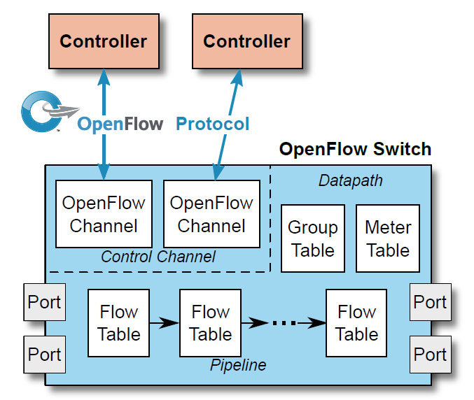
A basic SDN architecture diagram is shown in Figure 1 . We note how similar it is to the diagrams we saw for network management based control of optical networks.

Why are SDNs gaining popularity now?
As we have seen throughout this course the "pillars" that SDN rest on are not new to the networking community, however a collection of other factors are contributing to widespread interest in and some adoption of SDNs. One thing we will see is that SDNs offer increased flexibility in responding to existing and future network challenges. Such flexibility can be used to optimize network performance, increase network efficiency, or lower capital or operating costs.
Some of the trends that have accelerated the interest in SDNs:
- The rise of Ethernet switching & Merchant Silicon
- The rise of virtualization and soft switches
- The Open Source software movement and its effects
- A majority of large and small SDN controller projects are Open Source
- Many soft switches are open source, e.g., the Linux bridge and Open vSwitch.
- The most popular SDN test and development environment, Mininet, is open source.
- Open and widely accepted interfaces into the data plane
- The rise of data centers and their use of high performance "comodity" switches.
At the same time much software and computer hardware work has emerged over the last 20 years or so that can address concerns over SDN controllers as a single point of failure for a network. One much touted property of SDNs that is not on the previous "pillars" list is that of "centralized network control". From its very early days the Internet was based on distributed network control to avoid single points of failure and to allow partitioned portions of the network to continue to operate. Hence, from that perspective a move towards a more centralized control plane seems like it would result in a less reliable network. However, this isn't necessarily the case.
We should note that the distinction between the management plane and control plane isn't always clear and that network management systems have always been logically centralized. The key aspects of making any logically centralized system reliable are (a) avoiding dependence on a single hardware compute platform, (b) placing backup functionality at appropriate places in the network in case of disaster or network partitioning.
To avoid dependence on a single compute platform a number of high availability techniques can be used. In the "old days" such techniques required custom hardware and software. With the open source software movement much code and information is freely available:
- High Availability Linux, Linux-HA, http://www.linux-ha.org.
- Carrier Grade Linux
One of the key aspects of having a backup control site ready to take over in case of loss of the primary site is the replication of network state data at a reasonable level of granularity. We saw when we looked at data center applications that many traditional and NoSQL databases now commonly support such functionality.
Recommended Readings and Web Sites
Readings
-
One of the first papers folks should read is the original OpenFlow editorial piece [McKeown2008].
-
"The Road to SDN: An Intellectual History of Programmable Networks" [Feamster2014].
Very nice overview includes history and concepts. Students can skim over the section on "active networks". Very good sections on OpenFlow and Network Virtualization and how these relate to SDNs in general. Highly recommended.
-
Comprehensive Survey of SDNs from the proceedings of the IEEE [Kreutz2013]. A mammoth survey article. But be aware that the areas of software, standards, SDN controllers, and virtualization are moving very fast and hence there discussion may be slightly dated.
-
"FlowVisor: A network virtualization layer" [Sherwood2009].
Web Sites
- Open Networking Foundation
- Mininet. This is the preeminent SDN testbed network. Almost all SDN projects develop and test with Mininet. Mininet with based on Linux containers and written in Python.
- Ryu SDN controller. A full featured but lightweight and relatively easy to use OpenFlow controller written in Python. Also used in OpenStack network plugins.
- OpenDaylight OpenDaylight aims to be large enterprise/data center grade SDN controller/framework written in Java. It is based on the Java OSGi framework which permits many useful features. Unfortunately due to its size and steep learning curve I do not recommend OpenDaylight for early prototyping or exploration of SDN concepts.
- ONOS The Open Network Operating System (ONOS) aims to be a carrier grade SDN controller/framework. Like OpenDaylight it is based on a Java OSGi framework. Upper level softare architectural aspects differ. Due to a strong representation from telecommunications carriers on its board ONOS may have a greater emphasis on SDN support for the WAN.
The Southbound interface and OpenFlow
The OpenFlow controller to switch interface started as a proposal from a number of networking researchers in academia [McKeown2008] to make it easier for researchers to run networking experiments on real hardware in real networks. In particular they wanted the power of emerging high performance Ethernet switches. The idea behind OpenFlow is not to dictate a hardware implementation or architecture, but to provide an abstraction of hardware functionality that would be compatible with most switch hardware. From [McKeown2008]:
The basic idea is simple: we exploit the fact that most modern Ethernet switches and routers contain flow-tables (typically built from TCAMs) that run at line-rate to implement firewalls, NAT, QoS, and to collect statistics. While each vendor's flow-table is different, we've identified an interesting common set of functions that run in many switches and routers.
OpenFlow Protocol and Standardization
"OpenFlow, its like an assembly language for switches", Dr. G. Bernstein.
OpenFlow is a protocol to allow a controller to take advantage of advances in switch forwarding technology. The standardization of OpenFlow and related protocols moved from academia to the Open Networking Foundation. The OpenFlow Specifications are freely available for download. We'll first look at OpenFlow version 1.0 as this specification is easier to understand, we'll then look at some examples switching functions implemented with OpenFlow, finally we'll review the OpenFlow 1.5 specification to understand the current thinking.
OpenFlow Version 1.0
The basic OpenFlow reference model consists of a switch, a controller, and a secure channel between them. The switch is represented by a logical abstraction of a single flow table that performs packet lookup (header matching) and forwarding. Note that the actual switch hardware may be implemented differently.
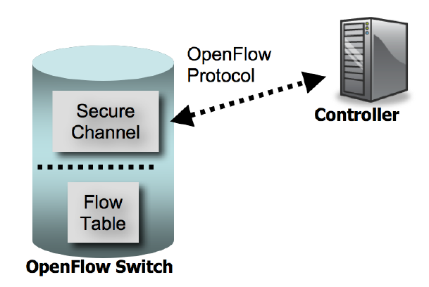
OpenFlow 1.0 Switch Model
The flow table contains three entries:
- header fields to match packets against
- counters to count packets that match a "flow" (header entry). These are also kept on a per port and per queue basis. See the specification for a complete list.
- actions to be performed on matching packets.
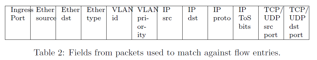
The header fields that can be matched against include: input port, Ethernet destination and source address, EtherType, VLAN id and priority, IP source and destination address, IP protocol, IP type of service bits, TCP/UDP source and destination ports.
In most cases we will only be in matching on a subset of these fields. To enable this OpenFlow supports "wildcards", i.e., ignoring a field or portion of a field for matching purposes. This could leave us with ambiguities over which flow entries to match when multiple entries containing wildcards could match. To resolve this each flow table entry also contains an associated priority.
From OFv1.0:
Packets are matched against flow entries based on prioritization. An entry that specifies an exact match (i.e., it has no wildcards) is always the highest priority. All wildcard entries have a priority associated with them. Higher priority entries must match before lower priority ones. If multiple entries have the same priority, the switch is free to choose any ordering. *Higher numbers have higher priorities.*
A list of zero or more actions are performed on a matched packet. These can include:
- Forward (requried)
- All sends the packet out all interfaces except the one it was received on.
- Controller Encapsulate and send the packet to the controller.
- Table Perform actions in flow table (packet out only)
- In port send the packet out the input port.
- Enqueue (optional) forwards a packet to a particular queue on a particular port.
- Drop (required)
- Modify-Field (optional) fields that can optionally be modified include:
- Set VLAN ID
- Set VLAN priority
- Remove VLAN header
- Modify Ethernet source or destination address
- Modify IPv4 source or destination address
- Modify IPv4 ToS bits
- Modify TCP/UDP source or destination port
OpenFlow 1.0 Protocol
The OpenFlow protocol utilizes Transport Layer Security (TLS) between controller and switch. Note that TLS commonly runs over TCP. There are three families of OpenFlow messages.
Controller-to-Switch
| Name | Abbreviation | Description |
|---|---|---|
| Features | switch_features | Used by the controller to ask the switch about which features its supports |
| Configuration | switch_config | Used to deal with non flow table configuration parameters. |
| Modify-State | flow_mod | Used to add and delete entries in the flow table. |
| Read-State | stats_request | Used to collect statistics (counters) |
| Send-Packet | packet_out | Used by the contoller to send a packet out a particular switch port |
| Barrier | barrier_request | Used to synchronize sets of switch operations. |
Asynchronous Sent from the switch to controller without a request.
| Name | Abbreviation | Description |
|---|---|---|
| Packet-In | packet_in | Use to forward packets to the controller. |
| Flow-Removed | flow_removed | Used to notify the controller that a flow was removed based on a timeout. |
| Port-Status | port_status | Indicates a port status change, e.g., port down. |
| Error | error_msg | Error message from switch. |
Symmetric These messages are sent by either controller or switch.
| Name | Abbreviation | Description |
|---|---|---|
| Hello | hello | Exchanged when the OpenFlow connection is established between switch and controller. |
| Echo | echo_request echo_reply | Echo request/reply messages are sent to determine liveness or latency of either side of the connection. |
| Vendor | vendor | A way for vendors to offer custom enhancements. |
SDN Networking Examples Part 1
Here we look at both specific examples and general networking features enabled by an SDN using OpenFlow 1.0.
Emulating an Ethernet Hub
So you are the proud owner of a virtual or real OpenFlow switch, what is the simplest way you can get it to forward any traffic? Note that some software OpenFlow switches without a controller attached will default to Ethernet bridge behavior. However, as we will see a fully featured Ethernet learning bridge requires a number of steps.
Return to the '90s: Ethernet hubs. Assuming a tree topology for all the switches in a network we can get them to forward traffic (rather inefficiently) by simply having them flood a packet out all ports except the one it was received on.
To implement such behavior takes only one flow table entry:
- Match: any packet; OpenFlow supports "wild cards" for any of the header fields see section 5.2.3 of OFv1.0.
- Action: Output All. From section 5.2.4 of OFv1.0 we see the "output" action and from section 5.2.1 (Port Structures) there are special "fake" output ports we could use either:
OFPP_FLOOD = 0xfffb, /* All physical ports except input port and those disabled by STP. */OFPP_ALL = 0xfffc, /* All physical ports except input port. */
A python code snippet implementing such "hub like" functionality via the POX controller is shown below.
def make_dumb_hubs(self):
    """ A command to turn wonderful OpenFlow enabled switches into dumb hubs"""
    msg = of.ofp_flow_mod()
    msg.priority = 1
    msg.actions.append(of.ofp_action_output(port=of.ofp_port_rev_map['OFPP_FLOOD']))
    for switch in self.switches.keys():  # Send the flow message to all switches
        connection = self.switches[switch]
        connection.send(msg)
A Simplistic Ethernet Learning Bridge
Let's outline the creation of an Ethernet learning bridge. We'll ignore special packets such as LLDP and Spanning tree protocol packets. We'll need the controller to keep track of all the switches and then for each switch we will need the following controller functionality:
-
For each switch the controller will keep a table mapping Ethernet source addresses to ingress ports, i.e., the ports we heard the address on. Call this table Eth_to_Port.
-
Install a low priority flow that matches any Ethernet destination address and forwards it to the controller with a flow_mod message. The controller gets a special port number:
OFPP_CONTROLLER = 0xfffd, /* Send to controller. */.This step isn't strictly necessary since the OFv1.0 states: "If no matching entry can be found for a packet, the packet is sent to the controller over the secure channel."
-
On receipt of an OpenFlow packet_in message perform the following steps:
- Record the source Ethernet and input port information into the Eth_to_Port.
- If the destination address is in the Eth_to_Port table do the following:
- Install a new flow with a flow_mod message with a match field containing the destination Ethernet address and action to forward it out the port from the Eth_to_Port table.
- Send a packet_out message with the received packet as data and the forwarding port from the Eth_to_Port table.
- If the destination address is not in the Eth_to_Port table. Send a packet_out message with the port set to
OFPP_ALL = 0xfffc.
IP Routing (Destination Based)
We can program our OpenFlow switches to perform IP routing (Layer 3 switching) based on destination IP addresses. Like OSPF and other IP control plane protocols the outcome of any SDN application for IP routing is a forwarding table at each switch with an entry for each destination IP address in the network along with the port to forward the matching packet.
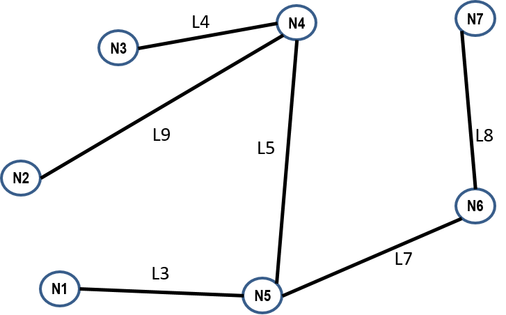
Such tables need to be consistent across switches to prevent packet loops. If we look at the union of the links used in all paths formed by the entries for a particular destination the "no loop" criteria implies that they must form a tree. In the case of OSPF the shortest path tree rooted on the destination node is used. This is an easy optimality condition and just as importantly makes sure that all OSPF routers compute consistent forwarding tables. In our SDN case we are computing/selecting the destination based trees in a centralized manner on the controller and hence can enforce the consistency of the switch tables, i.e., we'll be programming them.
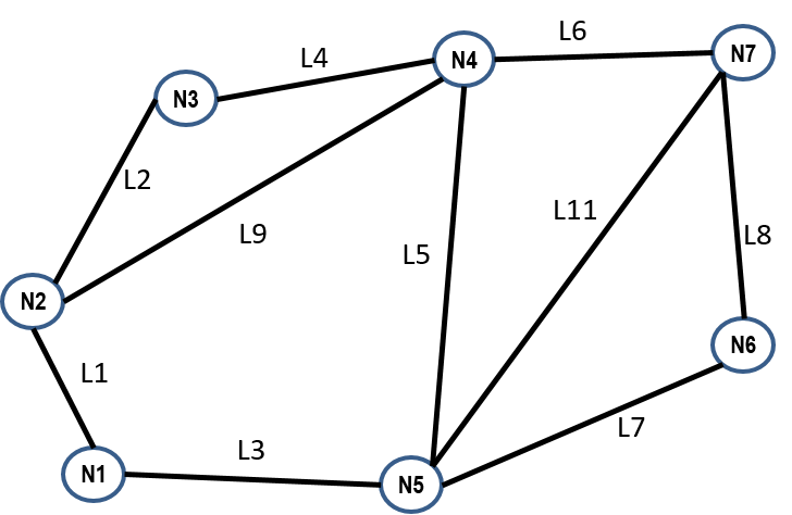
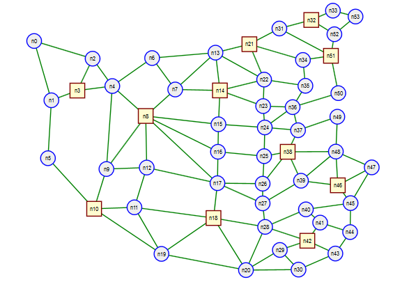
This brings up the question of how many different trees a network possess. There is an amazing theorem due to Kirchhoff that allows relatively easy computation of the number of trees if you have a good matrix algebra library handy. For example the network shown in Figure 4 has 79 distinct trees, while the network shown in Figure 6 has approximately $1.0303 \times 10^{23}$ distinct trees.
So lets review the tree choices in the different control planes we've seen so far:
- Ethernet Rapid Spanning Tree: Choose one tree for all network traffic to use.
- Ethernet Multiple Spanning Tree: Choose one potentially different tree for each VLAN to use.
- OSPF IP routing: Choose the shortest path tree for each different destination in the network. We get one particular tree for each destination.
- Most general approach (SDN enabled): Choose any tree in the network for each destination in the network.
A general approach to IP routing with SDN:
- Switches connect to the controller enabling the controller to know about all switches in the network.
- Using various discovery techniques (we'll look at one below) learn about all the links and end systems in the network, i.e., learn the complete network topology (graph) and destination addresses.
- For each destination choose a tree in the network from which to base all paths to that destination.
- For each switch we obtain the forwarding table entry for a destination by looking at the egress port for that switch on the destinations tree. In other words, each destination tree contains one flow table entry for each switch.
- Program switches with these entries.
Discovery via LLDP
The previous SDN approach to IP routing required discovery of links and host addresses. How can existing protocols and OpenFlow help us to do these operations?
To discover an Ethernet link we need a way of talking to our directly connected Ethernet neighbor. But how can we send a packet to them if we don't know their address? Won't any frame sent be flooded? To resolve these issues the IEEE specifies the Link Layer Discovery Protocol (LLDP) in IEEE 802.1AB.
First of all LLDP uses special group addresses as shown in Figure 7 .
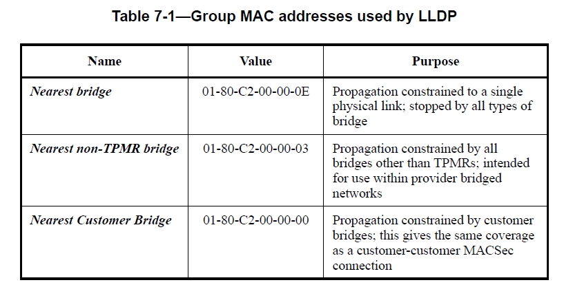
In addition IEEE 802.1D-2004 section 7.12.6 states "Frames containing any of the group MAC Addresses specified in Table 7-10 in their destination address field shall not be relayed by the Bridge." These are addresses in the range 01-80-C2-00-00-00 to 01-80-C2-00-00-0F and include the LLDP addresses previously mentioned. Hence these frames should never be flooded.
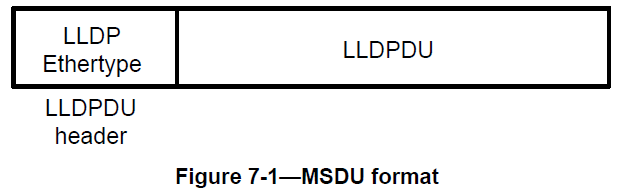
Second LLDP packets get their own Ethertype = 0x88-CC. IEEE 802.1AB-2009 section 7.4 then tells us we need a proper LLDP group address and LLDP Ethertype before considering the packet for LLDP processing.
Hence to receive LLDP packets at an OpenFlow controller we'd add a flow entry with match say the nearest bridge LLDP address of 01-80-C2-00-00-0E and an Ethertype = 0x88-CC. The action would be forward the packet to the controller (remember the special controller "port" from the learning bridge example). The controller would then be responsible for processing the LLDP packet.
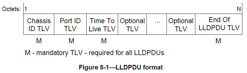
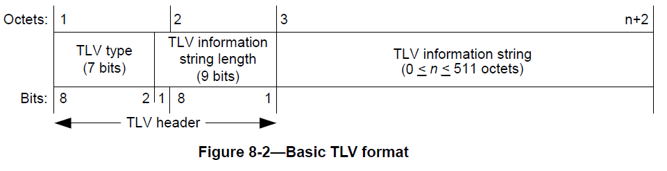
LLDP uses a very compact type-length-value (TLV) to convey neighbor information. The overall format of the packet, the required TLVs and their order and the TLV encoding is in the following Figures 8 , 9 , and 10 .
To do complete network discovery a controller would then need to:
- For every switch add a flow entry that matches all ports, the previously discussed LLDP group address and LLDP Ethertype and forward it to the controller.
- For each switch and each port on that switch the controller would generate an appropriate LLDPDU and send it out the associated switch port using an OpenFlow packet_out message.
- For each packet_in message check for LLDP group address and Ethertype if true then record information including received port and source address into a "network database".
Traffic Engineering without MPLS
We previously saw how to do general destination based routing with OpenFlow. We saw that we could choose any tree in the network to create the flow table entries for a particular destination. In Figure 11 below we show a network with the shortest path and widest path trees to a particular destination highlighted in red.
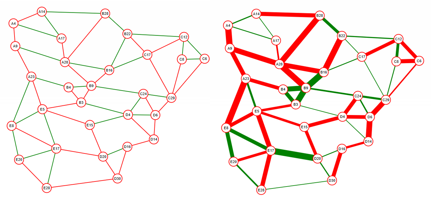
If the link cost is based on distance or hop count one of the advantages of using shortest path trees is that they tend to (a) reduce the communications latency (assuming similar or no congestion on all links), (b) they conserve overall link network bandwidth, i.e., fewer links carry the traffic when we use the shortest path.
In Figure 12 we show the shortest path and widest path between node E8 and D30. We see that the number of links used for the shortest path was three while for the widest path we used seven. This was due to the presence of the low bandwidth link D20-D30.
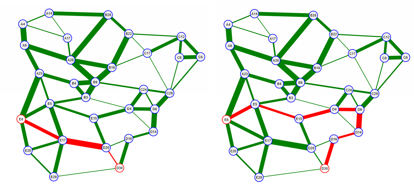
Hence it seems like overall we may not want to use widest path trees for general destination based routing. But what if the communications between E8 and D30 requires the additional bandwidth provided by the widest path? Can we set up a path for use just by this communication? Without MPLS? The answer is yes. But to do so requires that we perform our packet lookup based on source as well as destination addresses for the packet. If we wanted to specify paths for all communicating pairs that would require on the order of N^2^ table entries like we saw with MPLS however we can mix explicit paths and destination tree forwarding to reduce the flow table size. The general approach would be:
-
Establish a destination tree based forwarding regime
This can be a simple spanning tree learning bridge based regime (single tree for all destination) or a shortest path based regime (separate tree for each destination), or something else.
Assign all flow table entries using this scheme the same priority (used in matching).
-
For each communicating pair, say from nodes A to B, requiring a path with special properties
Compute or select a path from node A to B
For each switch along the path create a flow table entry based on a match to a source address of node A and a destination address of node B with forwarding out the appropriate port.
Assign each of these flow entries a priority higher than those used with the tree based regime. Note in OpenFlow higher priority matches take precedence and exclude lower priority matches.
If we only want specific types of traffic from node A to node B to follow a special path we can use more of the match fields available from OpenFlow. The key to being able to set up explicit paths via OpenFlow was the use of both source and destination address fields. An full example of this written in Python with the Ryu controller can be found in EthPathsBasic.py.
OpenFlow Beyond 1.0
We've been studying OpenFlow as it was first release at the end of 2009. Now let's take a look at how the specification has evolved. The quoted information and figures in this section are taken from the OpenFlow Switch Specification 1.5.1. In Figure 13 we show the OpenFlow architecture as of OFv1.5.
We see that this is a much more involved architecture than OFv1.0! We summarize key points in the OpenFlow Specification History in the following table.
| Version | Date | ID | Description/Highlights |
|---|---|---|---|
| 1.0 | 12/31/2009 | 0x01 | First official release. Features a single flow table model. A reasonable size set of match options and actions. |
| 1.1 | 2/28/2011 | 0x02 | Main fundamental enhancements: Multiple Tables, and Groups. Extensions for MPlS and VLAN tags, and virtual ports to support LAGs. |
| 1.2 | 12/5/2011 | 0x03 | Extensible match support, extensible set field support, IPv6 support. |
| 1.3 | 4/13/2012 | 0x04 | Much refactoring of the structure. Also included iwth this version are revisions 1.3.1 to 1.3.5 (3/26/2015). |
| 1.4 | 8/5/2013 | 0x05 | More extensible wire protocol. Also 1.4.1 (3/26/2015) |
| 1.5 | 12/2014 | 0x06 | Egress Tables, Packet type aware pipeline, extensible flow entry statistics, flow entry statistics trigger, and more... Also 1.5.1 (3/26/2015) |
Flow Tables
One of the biggest changes we see is that there can be multiple flow tables. Just as computer processors can make use of pipelining so can switches performing lookups and header processing. A very readable document justifying the need for and example uses of the multiple table model is ONF TR-510 on "The Benefits of Multiple Flow Tables and TTPs". One important point raised in this document is the major reduction in the total number of table entries that can be achieved for some important cases when multiple tables are employed.
From OFv1.5:
An OpenFlow switch is required to have at least one ingress flow table, and can optionally have more flow tables. An OpenFlow switch with only a single flow table is valid, in this case pipeline processing is greatly simplified.
In OFv1.5 A flow entry contains the following fields:
| Name | Description & Use |
|---|---|
| match fields | Used to categorize a packet into a flow. Includes port number, packet headers, and optionally information from a previous table if there is more than one. |
| priority | Matching precedence. The match field combined with the priority field are used to identify the table entry and must be unqiue. |
| counters | Keeps track of the number of time the flow has been matched. |
| instructions | Where the work gets done. These are specified in terms of a set of actions or modifications to the pipeline processing. |
| timeouts | Used to control how long until a flow is removed from the switch. |
| cookie | Yum! Not that kind of cookie :-(. A value used by the controller to help identify a flow, e.g., when filtering requests. Not used in packet processing. |
| flags | Used to manage flow entries. |
Matching Fields
Matching fields in OFv1.5 are specified via a type-length-value (TLV) format. This is similar but greatly expanded from the matches we saw for an MPLS forwarding equivalence class and OFv1.0. The types of matches available for the OpenFlow "basic class" is shown below:
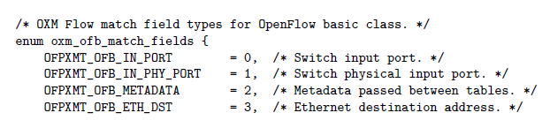
Operations: Instructions and Actions
One can look at OFv1.5 as containing two levels of operations (a) instructions and (b) actions. The upper level of operations that of instructions is particularly relevant to multiple flow table operation and not conceptually needed for single flow table operation. The table below gives a short summary of OpenFlow instructions to give you a rough appreciation for the functionality that they can be used to perform.
Instructions
From OFv1.5 section 5.1:
When processed by a flow table, the packet is matched against the flow entries of the flow table to select a flow entry. If a flow entry is found, the instruction set included in that flow entry is executed.
| Name | Req/Opt | Description & Use |
|---|---|---|
| Apply-Actions | Optional | Applies the specific action(s) immediately, without any change to the Action Set. This instruction may be used to modify the packet between two tables... |
| Clear-Actions | Required | Clears all the actions in the action set immediately. Support of this instruction is required only for table-miss flow entries... |
| Write-Actions | Required | Merges the specified set of action(s) into the current action set. Note that this is conceptually used in single table case. |
| Write-Metadata | Optional | Writes the masked metadata value into the metadata field. |
| Stat-Trigger | Optional | Generate an event to the controller if some of the flow statistics cross one of the stat threshold values. |
| Goto-Table | Required | Indicates the next table in the processing pipeline. The table-id must be greater than the current table-id. This instruction must be supported in all flow tables except the last one, OpenFlow switches with only a single flow table are not required to implement this instruction... |
Actions
From section 5.6 of the OF1.5 specification:
An action set is associated with each packet. This set is empty by default. A flow entry can modify the action set using a Write-Action instruction or a Clear-Action instruction associated with a particular match. The action set is carried between flow tables. When the instruction set of a flow entry does not contain a Goto-Table instruction, pipeline processing stops and the actions in the action set of the packet are executed.
In the table below we summarize some of the current actions supported by OpenFlow. See section 5.8 of the OpenFlow specification for more detail.
| Name | Parameters | Req/Opt | Description & Use |
|---|---|---|---|
| Output | Port # | Required | The Output action forwards a packet to a specified OpenFlow port... |
| Group | group id | Required | Process the packet through the specified group... |
| Drop | - | Required | Drop the packet. |
| Set-Queue | queue_id | Optional | The set-queue action sets the queue id for a packet. When the packet is forwarded to a port using the output action, the queue id determines which queue attached to this port is used for scheduling and forwarding the packet... |
| Meter | meter_id | Optional | Direct packet to the specified meter. As the result of the metering, the packet may be dropped (depending on meter configuration and state)... |
| Push-Tag/Pop-Tag | ethertype | Optional | Switches may support the ability to push/pop tags... |
| Set-Field | field_type value | Optional | The various Set-Field actions are identified by their field type and modify the values of respective header fields in the packet... |
| Copy-Field | src_field_type dst_field_type | Optional | The Copy-Field action may copy data between any header or pipeline fields... |
| Change-TTL | ttl | Optional | The various Change-TTL actions modify the values of the IPv4 TTL, IPv6 Hop Limit or MPLS TTL in the packet... |
Group Table
The group table consists of, surprise, group entries. The group entries have the following names and uses.
| Name | Description and Use |
|---|---|
| Group Identifier | a 32 bit unsigned integer uniquely identifying the group on the OpenFlow switch. |
| Group Type | Tells how the group is to be interpreted. See next table. |
| Counters | Counts the packets seen by this group. |
| Action Buckets | This is where things happen! "an ordered list of action buckets, where each action bucket contains a set of actions to execute and associated parameters." |
Group Types:
| Name | Req/Opt | Description & Use |
|---|---|---|
| indirect | Required | Executes the one bucket defined for the group. Used to simplify other processing. Example usage: default routes. |
| all | Required | Executes all buckets defined for the group. Example usage broadcast or multicast. |
| select | Optional | Executes one from all the defined buckets usually based on a computed hash or some type of round robin technique. Usage examples: Ethernet LAGs, IP ECMP, load balancing. |
| fast failover | Optional | Execute the first live bucket. Example useage link failure recovery schemes. |
SDN Networking Examples Part 2
MPLS Forwarding Example
Here we will give an example highlighting the MPLS support added in OpenFlow 1.1 and use it to set up MPLS LSPs between IP hosts across a network of OpenFlow 1.3 enabled switches.
-
To set up bi-directional communications between two IP hosts, say HA and HB, using MPLS we need to set up two unidirectional LSPs (Label Switched Paths) one from HA to HB and one from HB to HA.
-
Given a path for a uni-directional LSP the first switch is responsible for putting the IP packet received into the "LSP tunnel" for subsequent forwarding along the path. In MPLS terminology we need to define a Forwarding Equivalent Class (FEC) for this LSP.
-
At a minimum the FEC would consist of the destination IP address, but could also consist of the source IP address and possibly even the input port that is connected to the IP host.
-
The previously defined FEC turns into a OpenFlow "match" on the first switch on the path. Show below is a snippet from some python code that implements this match:
match_fields = {"in_port": get_in_port(g, node_list[0], node_list[1]),
        "eth_type": 0x800,
        "ipv4_src": g.node[src]['ip'],
        "ipv4_dst": g.node[dst]['ip']}
-
-
For each uni-directional link in our network that we wish to use for MPLS we must keep track of the MPLS labels being utilized. We will need to assign labels for each MPLS link along the LSPs path (except for the first and last which are IP links).
-
At the first switch we need to push and set the initial MPLS label. Some of the python code for doing this (OpenFlow actions) is shown below:
actions = [parser.OFPActionPushMpls(),
   parser.OFPActionSetField(mpls_label=plabel),
   parser.OFPActionOutput(
       get_out_port(g, node_list[1], node_list[2]))
] -
At each intermediate switch we just need to swap labels after we match on the appropriate input port and ingress label. Some of the python code for this match and actions is shown below:
match_fields = {
"in_port": get_in_port(g, node_list[i - 1], node_list[i]),
"eth_type": 0x8847,
"mpls_label": plabel
}
# other code ...
label_list = self.link_labels[(node_list[i], node_list[i + 1])]
olabel = assign_label(label_list)
labels_used[(node_list[i], node_list[i+1])] = olabel
actions = [parser.OFPActionDecMplsTtl(),
           parser.OFPActionSetField(mpls_label=olabel),
           parser.OFPActionOutput(get_out_port(g, node_list[i], node_list[i + 1]))]
plabel = olabel # output label becomes the next input label -
Finally at the last switch we need to pop the MPLS header so we can forward an IP packet to the IP host:
actions = [parser.OFPActionPopMpls(),
       parser.OFPActionOutput(get_out_port(g, node_list[i], node_list[i + 1]))]
-
-
To enable removal of LSPs when they are no longer needed we must keep track of all the SDN flows sent to switches associated with an LSP. This includes keeping track of which labels used on a link have been used by a particular LSP so we can reclaim those label resources when the LSP is removed.
The complete Python code (utilizing the Ryu controller) that sets up a pair of uni-directional LSPs (to give complete IP connectivity between two hosts) can be found in SimpleMPLS.py. You may be asking yourself: "why should I bother with MPLS when you previously showed my how to set up paths with SDN just based on source and destination?"
There are a number of good reasons that you might want to use MPLS mechanisms, first MPLS LSPs act as tunnels across a network and hence provide isolation and such, i.e., the MPLS network does not care about the IP addresses used by the hosts. Second the same LSP can be used for carrying traffic between multiple sources and destinations that originate/terminate on the same edge switches (LSP merging). We can also take advantage of MPLS label stacking (LSP hierarchies) to alleviate the $N^2$ problem that arises with source-destination based paths. Finally, by its virtual circuit nature MPLS can support a wide range of protection/restoration technques that provide various tradeoffs between speed, bandwidth efficiency, and robustness. For example see RFC3469 and MPLS local protection.
Implementations
As of 9/24/2015 products on the OpenFlow certified product list only included version 1.0 and 1.3 with a single table. However these are completed and shipping hardware products that have gone through a certification process.
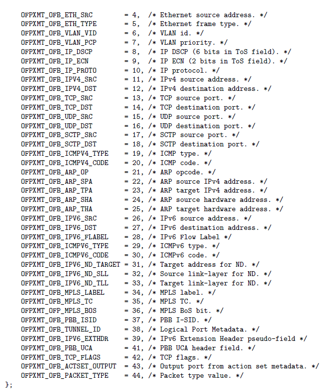
As could be expected merchant silicon vendors (chipmakers that do not sell their own switching gear) might be ahead of the equipment makers. For example Broadcom provides software for data plane abstraction to enable mapping of OpenFlow 1.3 with multiple tables into their latest hardware. In Figure 16 we show a diagram from Broadcom's data plane abstraction which uses multiple tables and claims OF1.3 compliance.
As an example of software based switches Open vSwitch OpenFlow support:
   Open vSwitch      OF1.0  OF1.1  OF1.2  OF1.3  OF1.4  OF1.5
   ###============   =====  =====  =====  =====  =====  =====
   1.9 and earlier    yes    ---    ---    ---    ---    ---
   1.10               yes    ---    [*]    [*]    ---    ---
   1.11               yes    ---    [*]    [*]    ---    ---
   2.0                yes    [*]    [*]    [*]    ---    ---
   2.1                yes    [*]    [*]    [*]    ---    ---
   2.2                yes    [*]    [*]    [*]    [%]    [*]
   2.3                yes    yes    yes    yes    [*]    [*]

   [*] Supported, with one or more missing features.
   [%] Experimental, unsafe implementation.
Open vSwitch supports multiple tables (but it's a bit difficult to find this fact in their literature). In their software release there is a tutorial that creates a full functionality VLAN aware learning bridge that uses multple tables. In fact they support the maximum allowed number of tables 255.
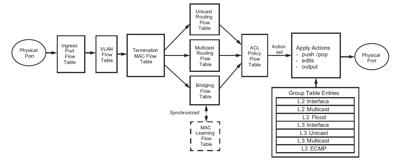
SDN Controllers and the Northbound Interface
As we've seen OpenFlow gives us access to modern switch functionality but at a level analogous to a computers assembly language. Currently there is much ongoing work in the area of SDN controllers, i.e., the software entities that control SDN enabled switches. Typicall conntroller duties include: registering switches, receiving messages, and sending instructions to switches. On top of many SDN controllers furnish additional general services/information such as network topology (obtained through a discovery process) and specific services such as BGP/SDN integration. Such higher level services (whether general or specific) are offered through what is called a northbound interface. At this time there are no well recognized standard (cross controller) interfaces of this type, i.e., all are controller specific.
Some of the more popular SDN controllers and their applications are:
- POX is a Python based OpenFlow controller. Although no SDN controller is particularly easy to work with POX seems to have one of the lower learning curves. POX documentation is relatively good but may require some digging. POX only supports OpenFlow v1.0.
- Ryu is another Python based SDN controller. Its advantages include support for OpenFlow v1.3 as well as others. Disadvantages: steeper learning curve.
- OpenDaylight is a very large open source project primarily written in the Java programming language. This is a Linux foundation collaborative project. Currently the documentation for OpenDaylight is significantly lagging behind the software itself. This fact and the Java technologies involved make for a rather steep learning curve and rendering OpenDaylight not very suitable for student projects. Another aspect of the steep learning curve is the use of YANG and NETCONF network management technologies as a basis for OpenDaylight interfaces and network models.
- ONOS is another open source large scale Java based SDN controller. However ONOS is aimed more at carrier applications rather than enterprise or data center applications.
Java Technology and SDN controllers
To create extensible, hot-pluggable, highly available SDN controllers both ONOS and OpenDaylight make use of an OSGi architecture. OSGi is a software component system for Java which support a number of useful features. In fact both ONOS and OpenDaylight utilize the same open source OSGi container system Apache Karaf.
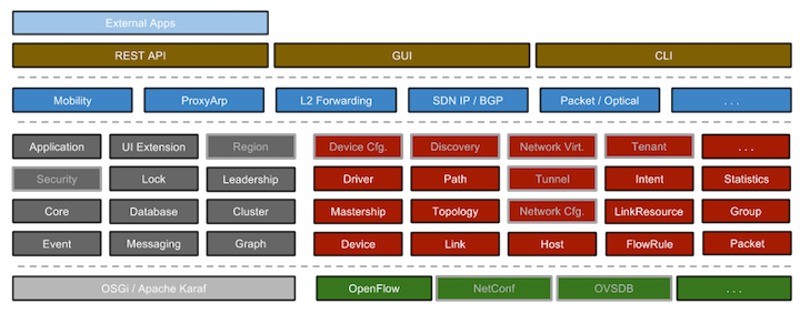
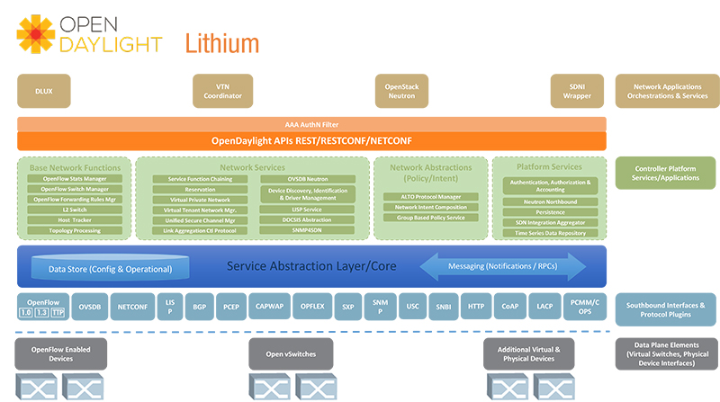
Software Diagrams for ONOS and OpenDaylight

Some other Useful SDN software tools
- Both OpenDaylight and ONOS rely on the LoxiGen tool to generate an OpenFlow library for Java.
LoxiGen is a tool that generates OpenFlow protocol libraries for a number of languages. It is composed of a frontend that parses wire protocol descriptions and a backend for each supported language (currently C, Python, and Java, with an auto-generated wireshark dissector in Lua on the way).
- OpenFlow switch test software that includes example of using the python loxi bindings to receive and send packets from python via a connection class. This uses python threading utilities and stuff that may require Linux underneath (OS dependencies).
Mininet: An SDN Development Environment
Mininet is a system for emulating a network with particular emphasis on SDNs. Mininet allows one to create a virtual network containing hosts, switches, links, and switch controllers. The technologies underlying Mininet are Linux namespaces and Linux control groups.
From the Mininet Overview page
Mininet can create kernel or user-space OpenFlow switches, controllers to control the switches, and hosts to communicate over the simulated network. Mininet connects switches and hosts using virtual ethernet (veth) pairs.
Linux Namespaces and Cgroups
From the Linux namespace overview: "The purpose of each namespace is to wrap a particular global system resource in an abstraction that makes it appear to the processes within the namespace that they have their own isolated instance of the global resource." Linux has six types of namespaces defined. Mininet uses the mount and network namespaces. Good sources of info on Linux namespaces:
- Overview of Linux namespaces
- API overview — More details on how these actually work. Such as the
unshare,setns, etc... - Network Namespaces — Most important for our purposes.
- Linux network namespace tutorial — A good tutorial with command line examples that you can try. You will generally need to use
sudobefore the commands he gives since modifying networking generally requires super user priveledges.
How Mininet Works
Mininet Hosts each get a network namespace
In excruciating detail:
Most of Mininet's direct work with Linux namespaces is in the C code file mnexec.c in the '/mininet/mininet' directory. Their call to unshare: unshare(CLONE_NEWNET|CLONE_NEWNS).
- In the python module
node.pytheHostclass is a direct descendant of theNodeclass without any additions or modifications. - As part of a
Nodes initialization it calls the thestartShellmethod.Nodehas the default constructor parameterinNamespace=True. startShellcalls themnexecexecutable with at least thenoption. This will start a process and put it into its own network namespace with theunshare(CLONE_NEWNET|CLONE_NEWNS)call.- Via the above procedure the new network namespace gets associated with the host via its process id (PID) and does not get a name. Hence we can have "nameless" namespaces on Linux and Mininet uses them. How's that for additional confusion!
For a CPULimitedHost Mininet uses Linux Cgroups. "cgroups (abbreviated from control groups) is a Linux kernel feature that limits, accounts for, and isolates the resource usage (CPU, memory, disk I/O, network, etc.) of a collection of processes." For example Mininet uses the cgget Linux command.
Mininet Controllers and Switches
Controllers and switches in Mininet by default do not get their own namespaces.
In excruciating detail:
- To create and run a mininet network the
Mininetclass from thenet.pyfile is used. - The
Mininetclass has a constructor parameterinNamespacewhich determines whether switches and controller are each put in their own network namespaces. This defaults tofalse. So controllers and switches do not get placed in separate network namespaces.
Mininet Links
Are created using Linux virtual Ethernet pairs.
Here's a snippet from the Mininet util.py file:
cmdOutput = runCmd( 'ip link add name %s '
                    'type veth peer name %s '
                    'netns %s' % ( intf1, intf2, netns ) )
This function was called by the Link class constructor in link.py. What this code is doing is calling the Linux ip link add command which is used to add virtual links.
For bandwidth limited links Mininet uses the Linux tc traffic control command with a token bucket filter tbf (really a traffic shaper) or other queueing discipline. To emulate link delay, jitter, and packet loss Mininet makes use of the Linux netem enhancement of Linux tc.
NetEm is an enhancement of the Linux traffic control facilities that allow to add delay, packet loss, duplication and more other characteristics to packets outgoing from a selected network interface. NetEm is built using the existing Quality Of Service (QOS) and Differentiated Services (diffserv) facilities in the Linux kernel.
For a nice overview with examples you can try from a Linux command line see this blog post on Mininet internals.
An SDN Approach to Network Virtualization
We've seen with OpenFlow versions 1.0 and 1.5 an enhanced and growing feature set that can offer functionality beyond what a standard Ethernet bridge or IP router might offer. These enhanced switching functions were added to support functions such as load balancing and firewalls. We first encountered such middleboxes when studying tunneling and VPNs. Some middleboxes are based on custom hardware working with proprietary or open source software.
As SDN switches become more flexible they can sometimes takeover the processing previously done in proprietary hardware enabling network functions that used to run on proprietary hardware to be run on programmable switches along with commodity servers. This then allows for similar flexibility in implementing network functions (e.g. load balancers, firewalls) as was seen with cloud computing. This emerging technique goes under the name network function virtualization. Note that it is the network hardware that is being virtualized, i.e., shared, and not the network functionality.
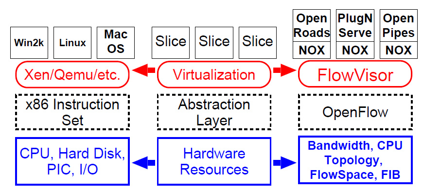
Finally we note that logically centralized network control can lead to new models and techniques for network virtualization [Sherwood2009], [Al-Shabibi2014]. In analogy with the hypervisor concept used for computer virtualization reference [Sherwood2009] introduces a "flowvisor" as shown in Figure 21 .
The way that this would work is that different SDN controllers for different user groups (tenants) would communicate via OpenFlow with the FlowVisor which lets them control OpenFlow switches in the physical network in a way that maintains isolation between the user groups. The steps to this process are illustrated in Figure 22 .
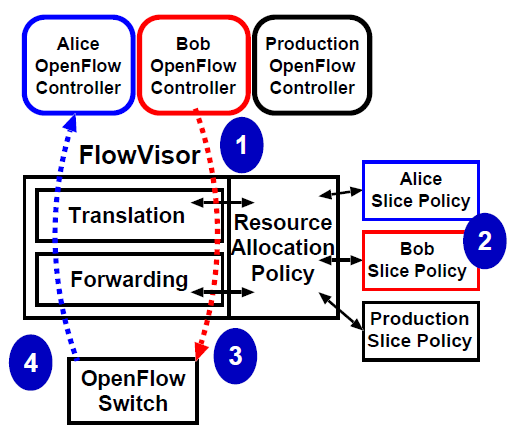
We see that the FlowVisor is given a policy with information on the different user groups and resources (switches and links) that they are allowed to use. Such information would also include address space information for the user groups which the FlowVisor would use to maintain isolation between the groups. Further research along these lines particularly on dealing with address space isolation can be found in [Al-Shabibi2014].
References
- [Kreutz2013] D. Kreutz, F. M. V. Ramos, en P. Verissimo, “Towards Secure and Dependable Software-Defined Networks”, in Proceedings of the Second ACM SIGCOMM Workshop on Hot Topics in Software Defined Networking, 2013, bll 55–60.
- [McKeown2008] N. McKeown et al., “OpenFlow: Enabling Innovation in Campus Networks”, SIGCOMM Comput. Commun. Rev., vol 38, no 2, bll 69–74, Mrt 2008.
- [Feamster2014] N. Feamster, J. Rexford, en E. Zegura, “The Road to SDN: An Intellectual History of Programmable Networks”, SIGCOMM Comput. Commun. Rev., vol 44, no 2, bll 87–98, Apr 2014.
- [Sherwood2009] R. Sherwood et al., “Flowvisor: A Network Virtualization Layer”, OpenFlow Switch Consortium, Tech. Rep, 2009.
- [Al-Shabibi2014] A. Al-Shabibi et al., “OpenVirteX: Make Your Virtual SDNs Programmable”, in Proceedings of the Third Workshop on Hot Topics in Software Defined Networking, 2014, bll 25–30.