Page Contents
Cloud Computing
Aren't networks "clouds"? If so, isn't any kind of access to remote computing resources over a network "cloud computing"? Sort of... For our purposes here, and in conformance with industry practice we'll be taking our definition of cloud computing from the U.S. government's National Institute of Standards and Technology (NIST). NIST got involved in the standardization of cloud computing since the U.S. government is a very large user of computing resources and can reap huge cost savings and other efficiencies with the migration to cloud based compute infrastructures.
From NIST's cloud website we get the following definition of cloud computing:
Cloud computing is a model for enabling convenient, on-demand network access to a shared pool of configurable computing resources (e.g., networks, servers, storage, applications, and services) that can be rapidly provisioned and released with minimal management effort or service provider interaction.
The cloud model has five essential characteristics:
- On-demand self-service — manual intervention is not required for normal changes to service.
- Broad network access — cloud services are made available via network access.
- Resource pooling — many resources are pooled to reap economies of scale.
- Rapid elasticity — there is the ability to scale up and down the amount of compute resources available to meet demand and remain energy/cost effective.
- Measured Service — resource usage is measured, typically on a time and type of resource used basis. There are a number of different pricing models offered by public cloud vendors.
Service Models
From the NIST Cloud Computing Reference Architecture come the definitions of the three cloud computing service models:
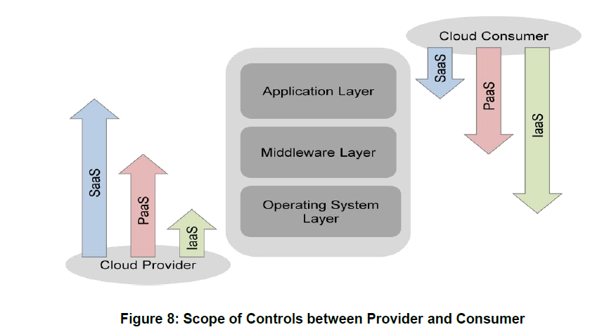
Software as a Service:
The capability provided to the consumer is to use the provider‟s applications running on a cloud infrastructure. The applications are accessible from various client devices through a thin client interface such as a web browser (e.g., web-based email). The consumer does not manage or control the underlying cloud infrastructure including network, servers, operating systems, storage, or even individual application capabilities, with the possible exception of limited user-specific application configuration settings.
Platform as a Service:
The capability provided to the consumer is to deploy onto the cloud infrastructure consumer-created or acquired applications created using programming languages and tools supported by the provider. The consumer does not manage or control the underlying cloud infrastructure including network, servers, operating systems, or storage, but has control over the deployed applications and possibly application hosting environment configurations.
Infrastructure as a Service:
The capability provided to the consumer is to provision processing, storage, networks, and other fundamental computing resources where the consumer is able to deploy and run arbitrary software, which can include operating systems and applications. The consumer does not manage or control the underlying cloud infrastructure but has control over operating systems, storage, deployed applications, and possibly limited control of select networking components (e.g., host firewalls).
Mini Quiz Match the following cloud services with one of the previous service models.
- Gmail
- My web hosting company. They furnish a wide variety of tools and languages, but I don't get to choose my operating system.
- An Amazon EC2 T2
t2.mediuminstance featuring 2vCPUof compute power and 4 GB of memory.
Question Did they leave something potentially important out of the above service model? What about Network as a Service, i.e., the ability to configure the network associated with compute resources for distributed applicaitons.
Deployment Models
From NIST
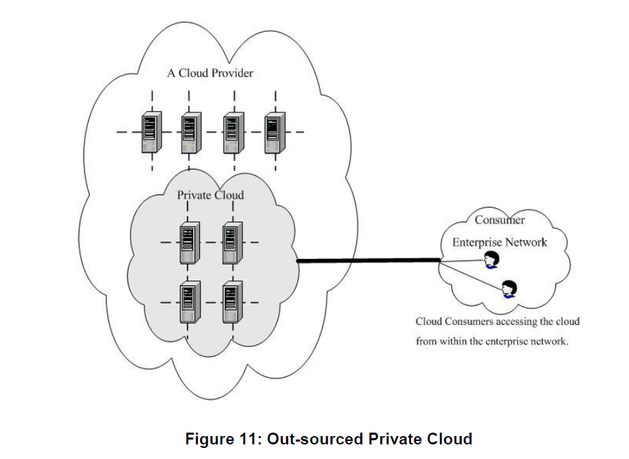
Private Cloud:
The cloud infrastructure is provisioned for exclusive use by a single organization comprising multiple consumers (e.g., business units). It may be owned, managed, and operated by the organization, a third party, or some combination of them, and it may exist on or off premises.
Community Cloud:
The cloud infrastructure is provisioned for exclusive use by a specific community of consumers from organizations that have shared concerns (e.g., mission, security requirements, policy, and compliance considerations). It may be owned, managed, and operated by one or more of the organizations in the community, a third party, or some combination of them, and it may exist on or off premises.
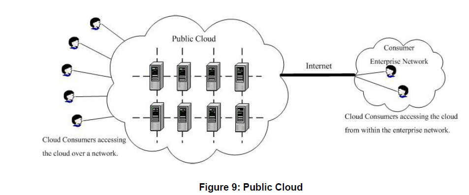
Public Cloud:
The cloud infrastructure is provisioned for open use by the general public. It may be owned, managed, and operated by a business, academic, or government organization, or some combination of them. It exists on the premises of the cloud provider.
Hybrid Cloud:
The cloud infrastructure is a composition of two or more distinct cloud infrastructures (private, community, or public) that remain unique entities, but are bound together by standardized or proprietary technology that enables data and application portability (e.g., cloud bursting for load balancing between clouds).
Example Public Cloud Providers
- Amazon Web Services
- Rackspace
- Verizon
- And many, many, more...
Data Center Hardware
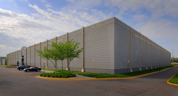
A data center can be just a few server machines tucked in the corner of a room, a moderately sized building, or mammoth facilities situated near large customers or low cost energy producers.
Within a data center we see racks and racks of equipment as shown below.
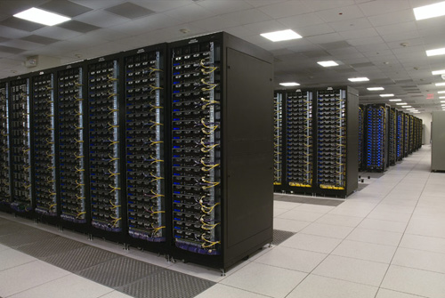
Since this is a networking class we won't delve into the structural and mechanical aspects of data centers. However we do note that equipment racks play an important role and that standardized rack designs are available via the OpenCompute projects OpenRack design.
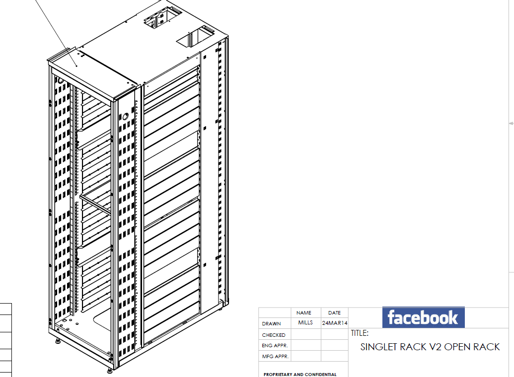
What do the servers look like that go into these racks? In Figure 7 show a diagram from an OpenCompute 2014 motherboard specification.
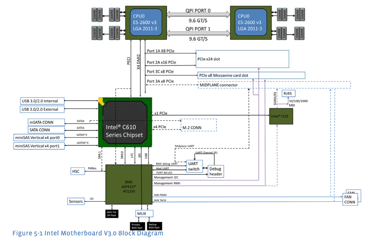
The processors used are specially designed for data center use. This particular family of Intel XEON processors which can contain from 6 to 18 processor cores. The design uses DDR4 memory and can accommodate up to 1024GB of memory.
"The motherboard uses SFP+ 10G Mezzanine card as its primary data network interface at I/O side." Translation: an extra card is attached to the motherboard to support 10Gbps Ethernet via the standard SFP+ optical interface connector. There is also an on board UTP based Ethernet controller.
Note that this particular motherboard specification was contributed to the OpenCompute project by facebook. An alternative example of an Intel based two socket datacenter server product can be found at QCT. It has a different form factor and different networking options such as dual port 1Gbps Ethernet or dual port 10Gbps Ethernet.
Cloud Applications
Most of the common network enabled applications we use every day are run in on a "cloud" and implemented in a data center residing somewhere on this planet. These include search engines such as Google, Bing, and Yahoo, network mail such as gmail, and various social networks such as Facebook, Pinterest, etc. To understand the demands that cloud computing places on data center networks we will take a quick look at two main types of applications: big data applications and modern web applications.
Big Data Example: Hadoop Ecosystem
What do we do when we have great quantities of data that we need to process in a variety of ways? Divide and conquer: Use many networked computers to work on the task! In this case we are not talking about using virtual machines (VMs) to share a single compute node, instead we are are throwing all the computing power of a set of available processors at a job. Examples of such tasks include web search, click through advertising analysis, recomender systems, and business analytics. Programming and coordinating the use of a set of networked compute resources is a fairly complex task, fortunately there is a growing list of open source software that can aid in getting the most of multiple compute resources.
One of the dominant open source ecosystems for such parallel processing on networked compute nodes is Apache Hadoop. See also Hadoop on Wikipedia. Here's just a small list of Hadoop users from the Hadoop wiki (note that this is volunteered information and may not represent current usage):
- Yahoo
-
More than 100,000 CPUs in >40,000 computers running Hadoop. Our biggest cluster: 4500 nodes (2*4cpu boxes w 4*1TB disk & 16GB RAM). Used to support research for Ad Systems and Web Search
-
- Hulu "13 machine cluster (8 cores/machine, 4TB/machine)"
- Adobe "We currently have about 30 nodes running HDFS, Hadoop and HBase in clusters ranging from 5 to 14 nodes on both production and development. We plan a deployment on an 80 nodes cluster."
- EBay "532 nodes cluster (8 * 532 cores, 5.3PB)."
- Facebook "Currently we have 2 major clusters: A 1100-machine cluster with 8800 cores and about 12 PB raw storage. A 300-machine cluster with 2400 cores and about 3 PB raw storage. Each (commodity) node has 8 cores and 12 TB of storage.
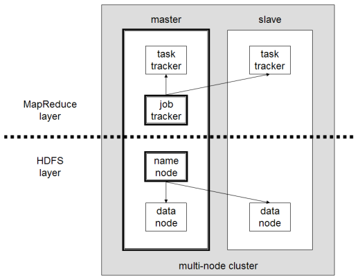
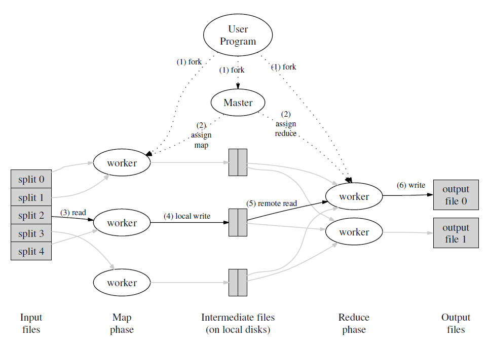
A highly simplified view of Hadoop is a two layer system consisting of Hadoop MapReduce running over the Hadoop File System shown in Figure 8.
MapReduce is functional programing model amenable to parallel computations. A widely cited paper [Dean2004] highlighted its use at Google and helped motivate the Hadoop project. Although we do not have time to go into much depth here we can illustrate the MapReduce approach with some of the functional programming features available in JavaScript. Suppose we wanted to compute the sum of the squares of the array of number shown below (try typing these in any modern web browser's developers tool console, ctl-shift-I):
t1 = [1, 2, 3, 4, 5]While there are many ways to do this operation some are more amendable to parallelization behind the scenes. JavaScript arrays have a map method that we can use to transform this array to another consisting of the squares of the elements:
square = function(x){return x*x;}
t1.map(square)  // This returns another array
Here we define a simple function to compute the squares. We then supply this function as an argument to the map method. The act of supplying functions as arguments to other functions is a key aspect of functional programming. The map method returns a new transformed array, in our case with all the squares of the elements of the original array.
The next step is to sum the elements of the array, for this we'll use the reduce method of JavaScript arrays.
sum = function(runSum, x){ return (x + runSum);}
// runSum is previous computation, x is array element
t1.map(square).reduce(sum, 0)  // 0 is the initial value fed to runSum
Now you won't be doing parallel processing on massive data sets in your browswer but here we are interested in the computational approach. If the the array was very large a smart processing system could take the map command and divide up the data and our map processing (applying our square map function) over multiple compute nodes. Similarly for the reduce stage. One such system that supports a programming syntax very similar to our simple JavaScript functional programming example is Apache Spark:
Apache Spark is a fast and general-purpose cluster computing system. It provides high-level APIs in Java, Scala, Python and R, and an optimized engine that supports general execution graphs. It also supports a rich set of higher-level tools including Spark SQL for SQL and structured data processing, MLlib for machine learning, GraphX for graph processing, and Spark Streaming.
Now back to describing Hadoop...
From HDFS Architecture we get the following nice description:
The Hadoop Distributed File System (HDFS) is a distributed file system designed to run on commodity hardware. It has many similarities with existing distributed file systems. However, the differences from other distributed file systems are significant. HDFS is highly fault-tolerant and is designed to be deployed on low-cost hardware. HDFS provides high throughput access to application data and is suitable for applications that have large data sets.
Notable features of the Hadoop File System from a networking perspective include:
- "Rack awareness: to take a node’s physical location into account while scheduling tasks and allocating storage."
- "Balancer: tool to balance the cluster when the data is unevenly distributed among DataNodes."
-
Hadoop MapReduce is a software framework for easily writing applications which process vast amounts of data (multi-terabyte data-sets) in-parallel on large clusters (thousands of nodes) of commodity hardware in a reliable, fault-tolerant manner.
-
A MapReduce job usually splits the input data-set into independent chunks which are processed by the map tasks in a completely parallel manner. The framework sorts the outputs of the maps, which are then input to the reduce tasks. Typically both the input and the output of the job are stored in a file-system. The framework takes care of scheduling tasks, monitoring them and re-executes the failed tasks.
Networking implications from Hadoop Wikipedia:
An advantage of using HDFS is data awareness between the job tracker and task tracker. The job tracker schedules map or reduce jobs to task trackers with an awareness of the data location. For example: if node A contains data (x,y,z) and node B contains data (a,b,c), the job tracker schedules node B to perform map or reduce tasks on (a,b,c) and node A would be scheduled to perform map or reduce tasks on (x,y,z). This reduces the amount of traffic that goes over the network and prevents unnecessary data transfer. When Hadoop is used with other file systems, this advantage is not always available.
Let's do some bandwidth and processing accounting:
- Assign nodes to mapping processing stage
- Move data to nodes, as needed, for the mapping stage of computation
- Perform mapping processing
- Select nodes for reduce processing
- Move data to nodes, as needed, for the reduce stage of computation
- Return final results to client
The biggest thing that stands out is that there is a lot of general node to node communications and that although there is a master node for coordinating the processing bulk traffic can flow between any two processing nodes. Hence we need to consider network architectures that will support this type of general data flow.
Modern Web Applications
Many classic web applications such as Word Press blogs and Drupal based sites are based on some type of LAMP software stack as shown in Figure 10.
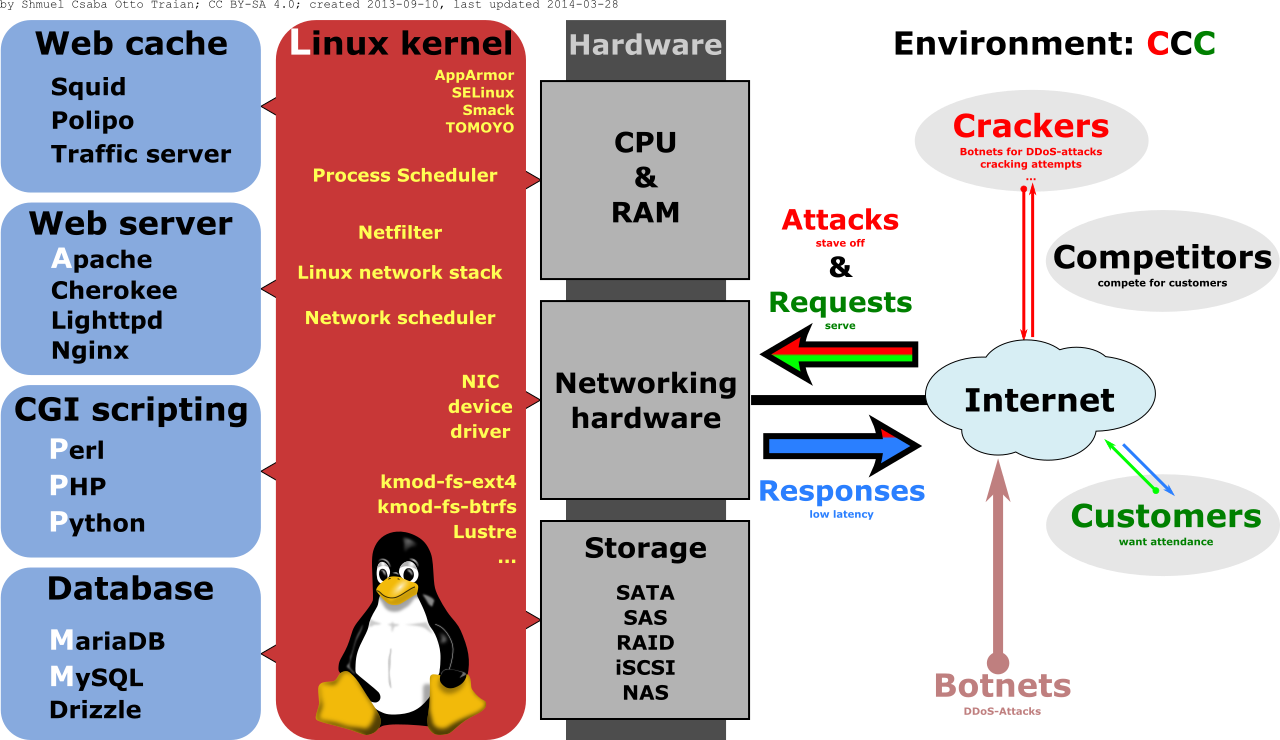
These pieces include:
- An operating system, classically Linux, on which to run the software components and furnish the networking stack.
- A web server, classically the Apache web server, but many other webservers are now used.
- A data persistence system, classically the MySQL database. This is needed for dynamic web sites for storage and retrieval of user and other data. Besides other relational database systems there are many choices with newer NoSQL databases.
- A programming language that works with the webserver to provide the application logic for dynamic requests. Classically this was done with the languages Perl or PHP but many other languages are popular on the server including Ruby, Python, server side Javascript, etc.
While a good starting poing for many applications the LAMP stack will run into a number of issues if the traffic volume to the website and/or the data storage needs of the web site grows. We'll look at a few of these issues to see how a single machine web application grows into a sophisicated networked distributed system consisting of many processing nodes with different functionalities. See scalable web architecture for more information.
Webserver throughput limitations
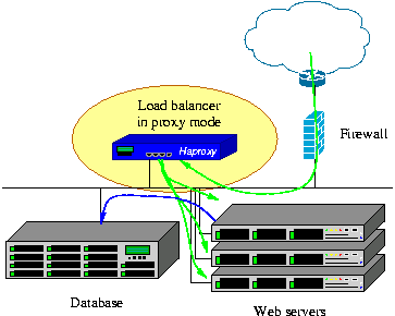
There is a limit to the number of TCP connections and the throughput that a single webserver can acheive. In addition the application processing logic may become a peformance bottleneck. One highly successful approach is to deploy multiple web servers running on multiple machines. To do this requires the addition of another functional element, that of a load balancer as shown in Figure 11. Here web service requests come in from the internet pass through the firewall and land at the load balancer which then distributes the requests amongst a set of web servers.
Load balancers are available in standalone boxes featuring hardware assistance and other features as well as via software only modules. Examples of software based load balancers include:
- The Nginx server operating as a load balancer. Shows simple configuration and discusses different load balancing techniques.
- HAProxy
HAProxy is a free, very fast and reliable solution offering high availability, load balancing, and proxying for TCP and HTTP-based applications. It is particularly suited for very high traffic web sites and powers quite a number of the world's most visited ones. Over the years it has become the de-facto standard opensource load balancer, is now shipped with most mainstream Linux distributions, and is often deployed by default in cloud platforms.
Speeding Data Access
Although long term persistent data needs to be stored to disk, disk access is quite slow compared to memory. For frequently changing data or for frequently accessed data it makes sense to keep this data in memory. These systems are known as in memory object stores and in memory object caches. Since there is a limit to how much data can be kept in one machines memory some of these provide for distribution of functionality over multiple nodes. Open source examples include:
- Redis key-value in memory object store or cache. They also have further information on their data partitioning approaches.
- Memcached distributed memory object cache.
Large Data Sets
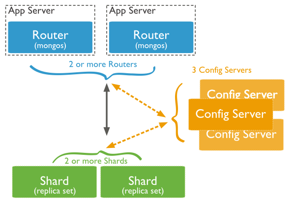
As we mentioned before disk access is much slower than memory access. However disk space is much larger and less expensive than CPU memory, so applications still will want and need to use disk based persistent storage. A single persistent storage server can become a performance bottleneck as well as a single point of failure reliability concern. Many enterprise scale database systems (SQL and NoSQL) offer facilities for data replication and/or partitioning (also known as sharding). As you might surmise this leads to more database server nodes supporting a web application. In Figure 12 we show an diagram of data partitioning from the MongoDB manual:
Examples of modern NoSQL databases with replication and/or partitioning features include:
- MongoDB: replication and partitioning (sharding).
- RethinkDB:replication and sharding.
- CouchDB: a replication based approach.
Summary
We've seen that a "simple" LAMP stack web application can grow into a multi-node networked distributed system within a data center. In addition, the number of actual nodes used will usually will depend on the demand for the application. This implies the need to rapidly bring up and take down compute nodes. In addition, for power savings and network bandwidth efficiency we may want to put compute nodes associated with a particular application on particular racks or move them to particular racks as the number of compute nodes grows and shrinks with demand.
Compute and Network Virtualization
Forms of Virtualization in Computing
Virtualization in computing relies on the fact that as computers grew more powerful they could simulate or emulate more and more aspects of compute operations. The list below is organized into increasingly sophisticated "virtualized" functionality that offers increasing amounts of isolation between the functionality being virtualized.
- Multiple tasks running at the same time. Also known as multi-threading. Which provides efficiency in the presences of blocking operations such as I/O. Multi-threading software shares the same memory space and provides minimal isolation amongst the threads.
- Multiple processes (multi-tasking) running at the same time. In this case each process gets its own protected memory and may get some service time guarantees.
- Multiple user operating systems such as Linux give the illusions to users that they each have their own computer while in fact they are sharing the same computer and operating system with other users. The operating system and hardware provide user and process isolation.
- Operating System-level virtualization
Operating-system-level virtualization is a server-virtualization method where the kernel of an operating system allows for multiple isolated user-space instances, instead of just one. Such instances (sometimes called containers, software containers,[1] virtualization engines (VE), virtual private servers (VPS), or jails) may look and feel like a real server from the point of view of its owners and users.
LXC (Linux Containers) is an operating-system-level virtualization environment for running multiple isolated Linux systems (containers) on a single Linux control host. The Linux kernel provides the cgroups functionality that allows limitation and prioritization of resources (CPU, memory, block I/O, network, etc.) without the need for starting any virtual machines, and namespace isolation functionality that allows complete isolation of an applications' view of the operating environment, including process trees, networking, user IDs and mounted file systems
-
In Hardware Virtualization multiple separate hardware platforms are "simulated" each of which we can run a completely separate and potentially different operating system. Popular software to do this on desktop and laptop computers include VMWare and VirtualBox. Emulated computers are known as Virtual Machines (VMs). Key and advanced features of modern hardware virtualization environments include:
- Snapshots/Pause — the ability to stop the virtual machine (VM) at any given point in time save its state and later restart the VM from that state.
- Migration — the ability to move a VM from one physical hardware machine to another continuing where the machine was previously paused.
- Failover — allows a "mirrored" VM to quickly take over from another in case of failure.
- Live migration — allows the migration of a VM with minimal downtime.
Virtual Networking
Virtual Network Interfaces
Now that we are able to virtualize compute resources (VMs) they will not be of much use to us unless we can attach these VMs to a network. To support tunneling protocols and such many operating system included the concept and implementation of virtual network interfaces. This was extended to VMs with the concept of virtual network interface cards called vNICs. Much innovation in software and hardware has occurred to make the efficiency of vNICs approach that of hardware interfaces.
Virtual Switches
What switching should be used when VMs using the same physical hardware wish to communicate? For efficiency sake such communication shouldn't have to use the physical NIC. To do this we would need some type of software based switch. The Linux kernel since version 2.4 has included the Linux Bridge which implements a subset of IEEE 802.1D functionality including the Spanning Tree Protocol. This allows Ethernet switching between both physical and virtual Ethernet interfaces.
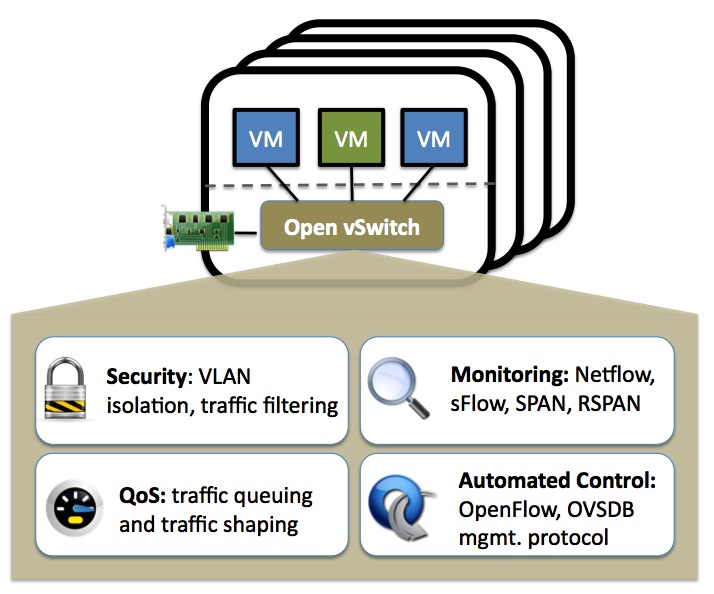
The Linux Bridge, however, isn't the only virtual switch available. Open vSwitch is a fully featured multi-layer switch which can be run on Linux and other environments. Look at the feature page and you'll see a number of items that we've already covered in this course as well as QoS, HFSC qdisc, Policing, and OpenFlow which we will be covering later.
It should be noted that since virtual switches on Linux can work with any virtual interfaces, they can work with interfaces created by Linux Containers (LXCs). Since LXCs are much lighter weight than VMs this makes it possible to emulate an entire network within an instance of the Linux operating system. This is the approach that Mininet uses.
Mininet can create kernel or user-space OpenFlow switches, controllers to control the switches, and hosts to communicate over the simulated network. Mininet connects switches and hosts using virtual ethernet (veth) pairs.
Data Center Networking
Network Topology
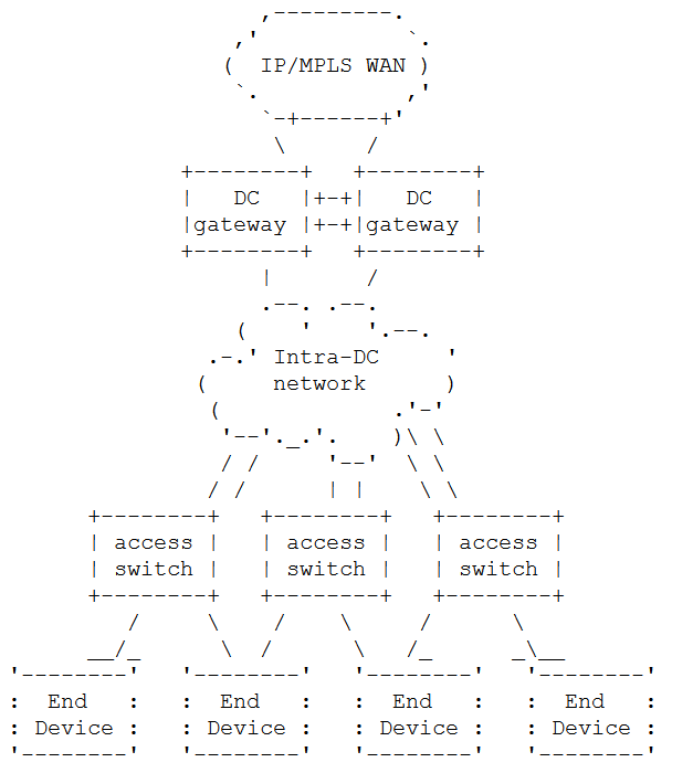
We've learned about cloud computing, data centers, network and compute virtualization, and data center hardware now its time to network the various pieces together and provide connectivity to the Internet or enterprise intranet. A generic diagram for this from RFC7365 is shown in Figure 14.
One possible implementation and what reference [Bari2013] calls a "conventional data center network topology" is shown in Figure 15.
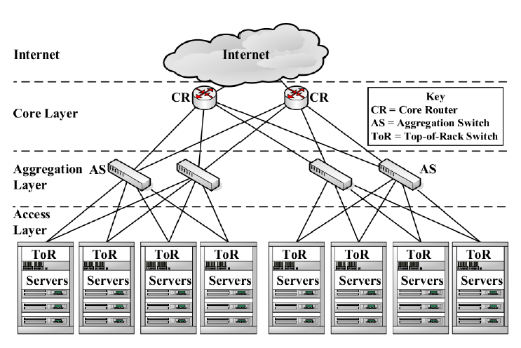
From this "conventional" data center topology and the generic data center network we can make a number of important observations:
- Racks are filled with servers hence we will want a least one switch per rack. In the conventional architecture this is called a top of rack (ToR) switch. In the generic diagram, Figure 14, the access switches serve this purpose.
- Losing communication to a rack can render take a fair number of servers offline, hence from the access switches to the intra-DC network (in the generic diagram) and from ToR switches to the aggregation switches (AS) (in the conventional diagram) we have multiple links to eliminate a single point of failure.
- By introducing additional links to avoid single points of failure we have by necessity created loops in our network topology. This could lead to packet loops. There are a number of options to deal with this problem.
- For an all Ethernet switching network a spanning tree protocol to select a "tree" and disable non-tree links. In case of link failure the protocol will recompute a new "tree" and enable previously disabled links as needed.
- Perform all switching at the IP layer, i.e., just use Ethernet for point to point links. The IP routing protocol will compute the shortest paths (which form a tree) and loops will be avoided.
- With a hybrid L3/L2 switching network such as the "conventional" data center network ensure that the Ethernet subnets have no loops and only provide redundant connectivity via IP layer routing.
- Data center networks are bandwidth hungry and the preceding loop avoidance schemes implicitly or explicitly turn off a subset of the networks links to traffic. There are a number of ways to avoid this.
- For an Ethernet network supporting multiple VLANs one can use the Multiple Spanning Tree Protocol (MSTP) to set up multiple trees in the network and assign their use to specific VLANs. Note that this can help to further isolate one VLANs traffic from another. An example of optimizing MSTP tree selection and assignment can be found in [Ho2011].
- If an IP approach is used to avoid loops then Equal Cost Multi-Path (ECMP) can be used. In fact a recent internet draft on "Use of BGP for routing in large-scale data centers" by Facebook and Arista has a section devoted to ECMP.
- Use techniques such as MPLS or SDN to set up traffic engineered flows.
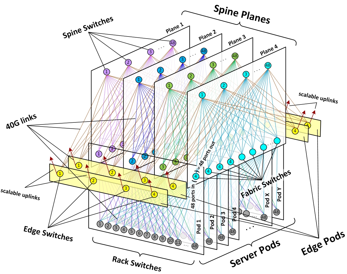
- We see that the conventional network includes another level of switching hierarchy which they call the "core layer". Such additional layers are common and we will learn about the theory behind them when we study advanced switch architectures. As an extremely high performance data center networking architecture example see Figure 16 below from Facebook.
Traffic Types, Isolation, and Network Services
There are a number of different traffic types that can be found within a data center including:
- Guest/Tenant traffic: This is traffic running between multiple VMs belonging to the same tenant. As we saw in the discussion of modern web applications the number of VMs in use by tentant and the traffic between them can vary greatly over time.
- Management traffic: This traffic is responsible for placement, creation, migration, and deletion of VMs, guest networking configuration, and systems monitoring, etc... This traffic is critical to the operation of the data center and should be isolated from all other traffic. This isolation may include using separate physical NICs.
- Public traffic: This is traffic to and from the internet bound for VMs in the data center. Such traffic generally needs to go through firewalls and should be monitored by intrusion detection software.
- Secondary storage traffic: For data centers offering VM instances as compared to data centers running Hadoop and other "big data" processing, VM images, templates, and ISO images for operating systems represent large chunks of data that need to be moved. It can be highly desirable to isolate the other traffic types from such flows to avoid service delays.
Network services may include:
- Shared Layer 3 networking with assigned private/public IP addresses per VM. This was the type of networking service initially offered in AWS's EC2 cloud.
- Private Layer 2 networking with user choice of private IP addresses and assigned public IP addresses.
- Private Layer 2 VLAN networking with user assignment of its own VLANs to its different VM as well as virtual routers to connect these VLANs.
- More advanced forms of network virtualization based on SDN such as described in [Sherwood2009], [Al-Shabibi2014], or OpenVirtex.
Option 1 above can be realized via conventional Ethernet/IP networking techniques; Option 2 can be realized via Ethernet VLANs subject to the constraint of a maximum of approximately 4096 tenant LANs. Options 3 and 4 require more advanced techniques. In the next section we'll look at an alternative approach to support options 2 and 3. We'll touch a bit on option 4 when we study SDNs.
Network Virtualization over Layer 3
The IETF has undertaken an effort to standardize an approach to providing data center network virtualization over IP. Although formal standards do not yet exist there are some very helpful documents (informational RFCs) describing the multi-tenant data center problem space in detail RFC7364, a framework for solutions RFC7365, and some specific tunneling protocols that have been used to implement overlays VXLAN, RFC7348.
The abstract of RFC7364 outlines the problem space as follows:
This document describes issues associated with providing multi- tenancy in large data center networks and how these issues may be addressed using an overlay-based network virtualization approach. A key multi-tenancy requirement is traffic isolation so that one tenant's traffic is not visible to any other tenant. Another requirement is address space isolation so that different tenants can use the same address space within different virtual networks. Traffic and address space isolation is achieved by assigning one or more virtual networks to each tenant, where traffic within a virtual network can only cross into another virtual network in a controlled fashion (e.g., via a configured router and/or a security gateway).
In the document they highlight some of the problem areas we have discussed and some new ones. Overall they mention:
- Dynamic provisioning (which we have already discussed)
- VM Mobility Limitations: Live migration of virtual machines may not be possible if IP or Ethernet addresses need to be changed based on the new VM location. In addition, some software licenses are based on Ethernet addresses.
- Forwarding Table Size Limitations: Modern multi-core servers can support many VMs, each of these will need an Ethernet and one or more IP addresses. This can put a strain on the forwarding tables of top of rack (ToR) and other data center switches.
- Need for address separation between virtual networks.
- Need for address separation between virtual networks and data center network infrastructure.
The Overlay Solution Approach
In the network virtualization over IP approach the "underlay" network used to actually forward traffic is an IP network. The tenants see either their own isolated IP network or isolated Ethernet/IP network.
The basic reference model is shown in Figure 17.
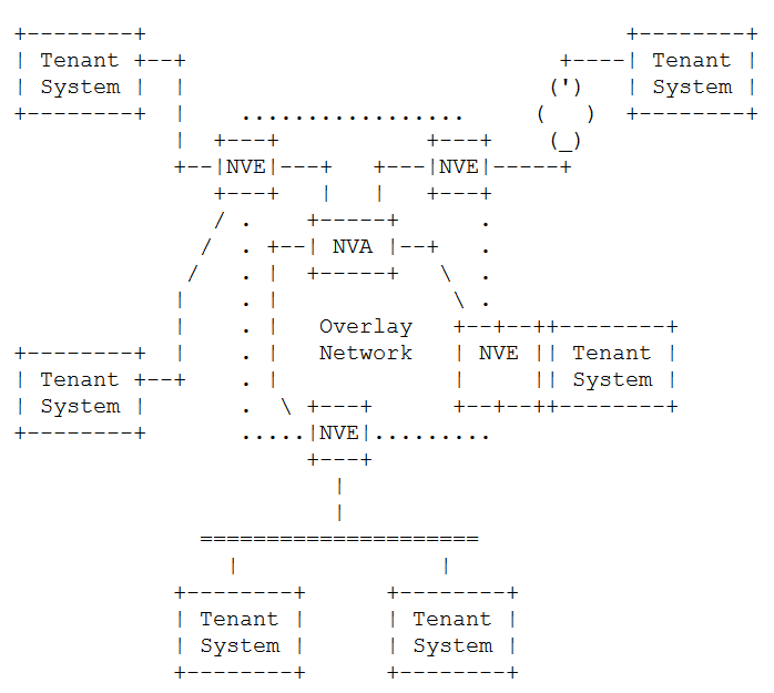
The following definitions needed to understand this diagram are from [RFC7365]:
Network Virtualization Edge (NVE): An NVE is the network entity that sits at the edge of an underlay network and implements L2 and/or L3 network virtualization functions. The network-facing side of the NVE uses the underlying L3 network to tunnel tenant frames to and from other NVEs. The tenant-facing side of the NVE sends and receives Ethernet frames to and from individual Tenant Systems. An NVE could be implemented as part of a virtual switch within a hypervisor, a physical switch or router, or a Network Service Appliance, or it could be split across multiple devices.
Network Virtualization Authority (NVA): Entity that provides reachability and forwarding information to NVEs.
It is hard to offer a clearer description of the processing involved than that present in section 4.1 of RFC7364 so we will quote it below for easy access.
The idea behind an overlay is quite straightforward. Each virtual network instance is implemented as an overlay. The original packet is encapsulated by the first-hop network device, called a Network Virtualization Edge (NVE), and tunneled to a remote NVE. The encapsulation identifies the destination of the device that will perform the decapsulation (i.e., the egress NVE for the tunneled packet) before delivering the original packet to the endpoint. The rest of the network forwards the packet based on the encapsulation header and can be oblivious to the payload that is carried inside.
Overlays are based on what is commonly known as a "map-and-encap" architecture. When processing and forwarding packets, three distinct and logically separable steps take place:
-
The first-hop overlay device implements a mapping operation that determines where the encapsulated packet should be sent to reach its intended destination VM. Specifically, the mapping function maps the destination address (either L2 or L3) of a packet received from a VM into the corresponding destination address of the egress NVE device. The destination address will be the underlay address of the NVE device doing the decapsulation and is an IP address.
-
Once the mapping has been determined, the ingress overlay NVE device encapsulates the received packet within an overlay header.
-
The final step is to actually forward the (now encapsulated) packet to its destination. The packet is forwarded by the underlay (i.e., the IP network) based entirely on its outer address. Upon receipt at the destination, the egress overlay NVE device decapsulates the original packet and delivers it to the intended recipient VM.
Comments As we can see the basic operation that supports NVO3 is encapsulation and tunneling very similar to what we've already encountered with IP-in-IP, GRE, L2TP, and MPLS. We also need to realize that the configuration of the NVEs is a significant task that requires automation for all but trivial situations.
Yet Another Tunneling Protocol: VXLAN
Now let's take a look at a tunneling protocol that was specifically created to support network virtualization in data centers, the Virtual Extensible LAN (VXLAN) protocol. Although not an IETF standard VXLAN is documented in the informational RFC7348.
Based on what we already know about creating a flexible tunneling protocols and the current limitations of Ethernet VLANs one might even guess the two key aspects of VXLAN:
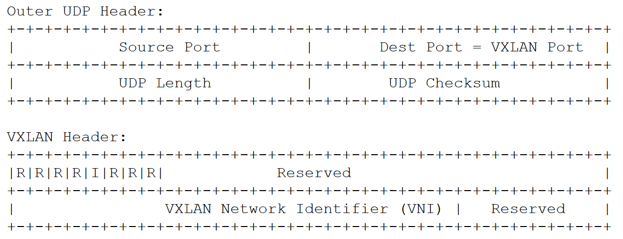
- VXLAN runs over UDP. It uses the well known (destination) port 4789.
- The VXLAN header includes its own VXLAN Network Identifier (VNI) which serves to identify a virtual network. They made this field 24 bits long, good for over 16 million virtual networks.
- The VXLAN payload is the clients Ethernet frame excluding the frame check sequence.
The format of the outer UDP and VXLAN headers are shown in Figure 18.
As we mentioned before when using IP routing as a basis for data center switching the use of ECMP is important to make good use of bandwidth available on all working links. This poses somewhat of a challenge when using tunneling. Here is how RFC7348 addresses the problem:
Source Port: It is recommended that the UDP source port number be calculated using a hash of fields from the inner packet -- one example being a hash of the inner Ethernet frame's headers. This is to enable a level of entropy for the ECMP/load- balancing of the VM-to-VM traffic across the VXLAN overlay. When calculating the UDP source port number in this manner, it is RECOMMENDED that the value be in the dynamic/private port range 49152-65535 [RFC6335].
We see here that in order for ECMP hashes to work on the router some hash visible field such as UDP ports must change. Since the destination port is needed to "demultiplex" the UDP packet to the VXLAN endpoint this leaves the UDP source port as the only field that can be varied.
We note that VXLAN is not the only approach to network virtualization tunneling other approaches include GRE, STT. This is an area of current study at the IETF.
References
- [Dean2004] J. Dean en S. Ghemawat, “MapReduce: Simplified Data Processing on Large Clusters”, in Proceedings of the 6th Conference on Symposium on Opearting Systems Design & Implementation - Volume 6, 2004, bll 10–10.
- [Bari2013] M. F. Bari et al., “Data Center Network Virtualization: A Survey”, Communications Surveys & Tutorials, IEEE, vol 15, no 2, bll 909–928, 2013.
- [Ho2011] T.-V. Ho, Y. Deville, O. Bonaventure, en P. Francois, “Traffic Engineering for Multiple Spanning Tree Protocol in Large Data Centers”. 2011.
- [Sherwood2009] R. Sherwood et al., “Flowvisor: A Network Virtualization Layer”, OpenFlow Switch Consortium, Tech. Rep, 2009.
- [Al-Shabibi2014] A. Al-Shabibi et al., “OpenVirteX: Make Your Virtual SDNs Programmable”, in Proceedings of the Third Workshop on Hot Topics in Software Defined Networking, 2014, bll 25–30.